 (CLICK ON PICTURE FOR FULL SIZE VIEW)
MAKING NEW METER SCALES
P. Wokoun, 8/2008
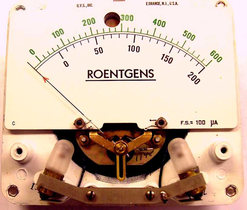
When making a new meter scale I usually plan to follow the original meter's scale size, i.e. the same angular movement from zero to full scale and the same arc location on the scale. It's relatively simple to revise the number of divisions, the style of division markings, as well as the font sizes. The meter we're using as an example here is some oddball one I had lying around. I am going to change the scale to make it an expanded scale DC voltmeter with a 10 to 15 volt range. I remove all internal resistors and shunts and attach the meter movement directly to the external terminals.
For tools I use a couple of 6-inch stainless steel rulers with graduations up to 1/64-inch and a 6-inch protractor.
This exercise is not going to get into how to open up the meters and gain access to the meter scale. I couldn't possibly cover all the types; you have to use your skill in opening them up. This process starts with you having the meter opened up BEFORE the meter scale is removed.
(CLICK ON PICTURE FOR FULL SIZE VIEW)
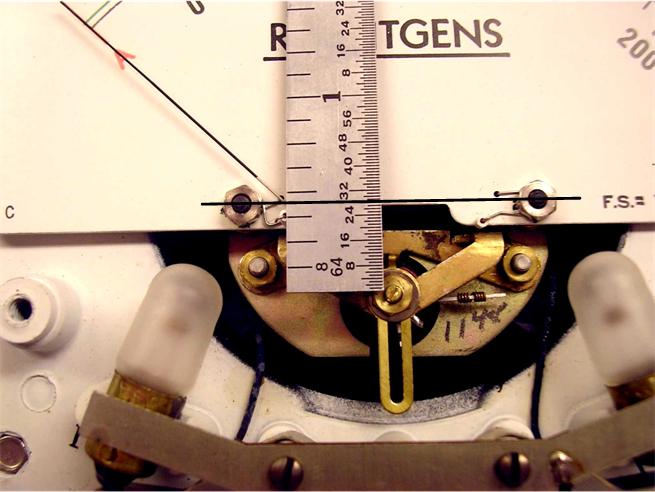
Using the ruler we need first to measure any offset between a line drawn between the two meter scale mounting screws and the meter movement's axis of rotation. This axis of rotation is centered behind the movement's front tension screw. Try and measure any offset to the nearest 1/64. My experience is that most meter scale mounting screws line up with that front tension screw but the example we're using doesn't. Also measure the distance between the mounting holes. The front tension screw is almost always centered between the mounting holes but if not, make careful measurement of their locations.
 (CLICK ON PICTURES FOR FULL SIZE VIEWS)
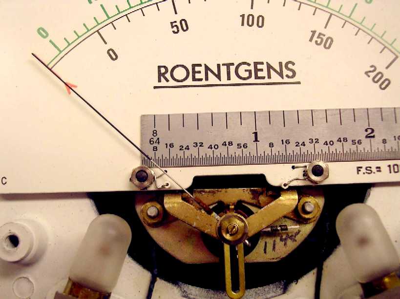
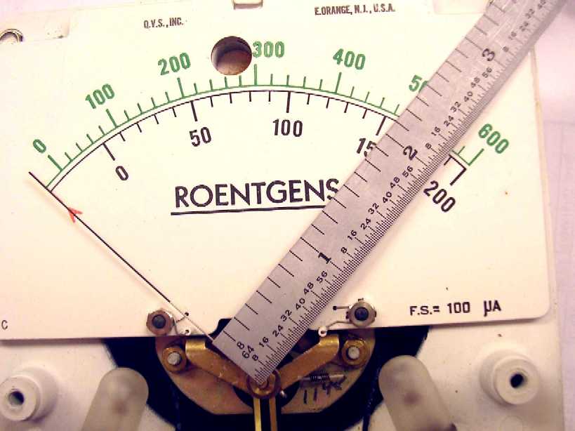
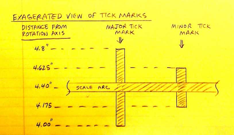
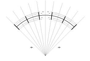
Now measure from the rotation axis to the beginning and end of all the different tick marks as well as the scale arcs.
 (CLICK ON PICTURE FOR FULL SIZE VIEW)
Now you can carefully remove that meter scale. Be careful you don't snag the pointer; the movements are very fragile.
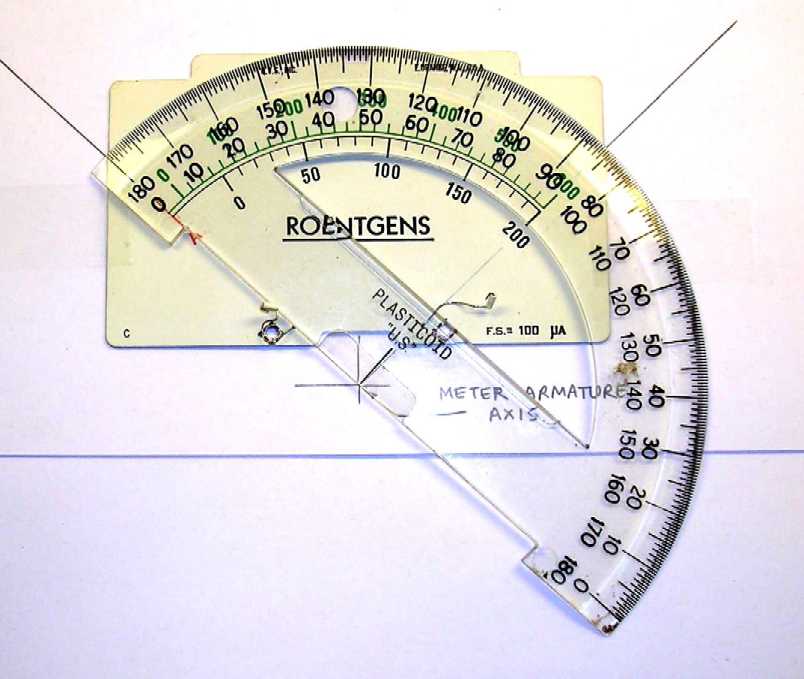
I then tape the meter scale to a sheet of paper. Draw in where the rotation axis is located. Then draw lines from the rotation axis through both zero and full scale tick marks to somewhat beyond the scale. Using the protractor measure the angular distance between the zero and full scale tick marks. Most meters are about 90 degrees, some are 100 degrees, while our example here turns out to be about 93.5 degrees.

 (CLICK ON PICTURES FOR FULL SIZE VIEWS)
I am going to modify the finished product a little and make the scale arc only 90 degrees. This is only because the numbers come out easier to show. I could use the full 93.5 degrees and just take the math out to a couple more decimal places.
The meter example here has two scale arcs but the finished product is only going to have one centered somewhat between the two.
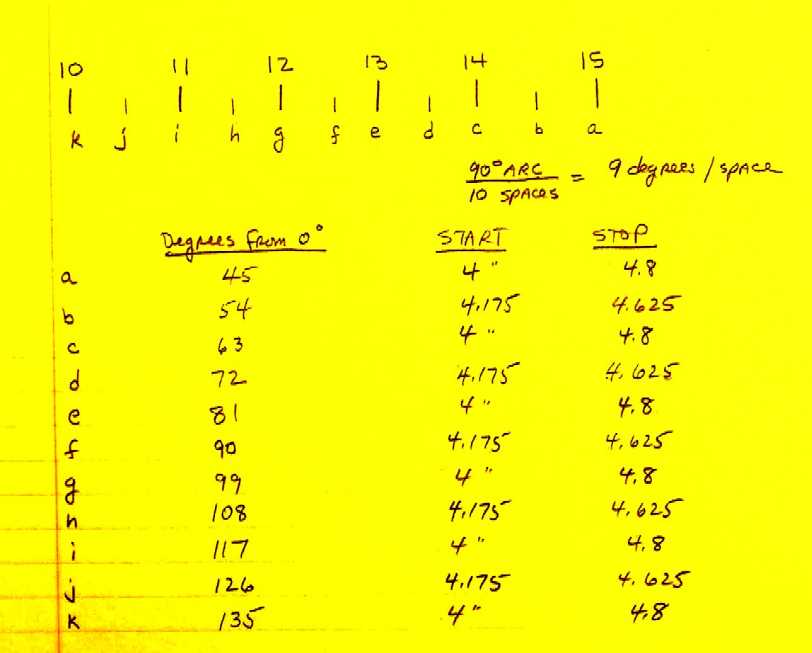
On another sheet of paper I start a table where I do all the calculations. First, you need to determine what kind of scale you want: from what to what and how many major and minor tick marks between them. For our example here I decided on an expanded voltmeter scale from 10 to 15 volts DC, with major tick marks on the unit volts and minor tick marks at the 1/2 volt points. You can go as fancy as you want here, for example, using half-major tick marks at the 1/2 volt points and minor tick marks at each 1/10 volt point. Remember, more divisions make it harder to read and your meter's accuracy may not support that kind of linearity, especially the cheaper ones. Across the top of this sheet I draw the scale and label each tick mark. To determine how many degrees will between each tick mark, divide the total scale arc you're going to use by the number of spaces between the zero and full scale tick marks. On our example here we're going to use a 90 degree arc and since we have 10 spaces, each tick mark will have 9 degrees between them.
 (CLICK ON PICTURE FOR FULL SIZE VIEW)
On our table, I label the first column TICK MARK NUMBER, the second column is VISIO DEGREES, the third column is TICK MARK START DISTANCE, and the fourth column is TICK MARK STOP DISTANCE. For our example meter since I elected to use a 90 degree scale arc, the meter's halfway point of 12.5 volts will be exactly in the center or at the 45 degree scale arc point (straight up). In Visio drawings degrees are measured from the right horizontal line and increasing counter-clockwise. So our straight up tick mark at 12.5 volts will be at 90 degrees as measured in Visio. Since we calculated a 9 degree spacing between tick marks previously, the second column in our table can be completed. Starting at the 12.5 volt tick mark at 90 degrees, subtract 9 degrees for each tick mark going towards the full scale mark and add 9 degrees for each tick mark going towards the zero tick mark. Now you have a listing in Visio-degrees where all the tick marks will be located.
 (CLICK ON PICTURE FOR FULL SIZE VIEW)
In Visio circular dimensions are entered as diameters. You have to remember the distances you measured on the meter scale to the scale arcs and tick marks are radii and you have to double them when entering in Visio. So in our table for columns three and four you can enter the major and minor tick mark start and stop distances from the rotation asis. Some minor adjustments can be done here to make the marks centered on the scale arc.
 (CLICK ON PICTURE FOR FULL SIZE VIEW)
With the table filled out we can now move to Visio and start drawing our new scale.
I've had no training in Visio, just a bunch of self taught knowledge. So I'm sure there are easier way to do things which I'm not aware of. I just found a way to accomplish what I wanted to do. If you know of any easier way to do it, let me know & I'll try it. I'm presently using Visio Technical 5.0c Plus so other versions may vary to some extent with their capabilities.
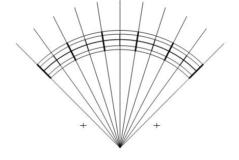
In Visio we're going to start with a new drawing sheet. Most of what we use will be on the drawing toolbar. Keep the drawing scale at 1 to 1. Insure the page size is 8.5 x 11 and the bullet 'same as printer' is selected. I like to reset the zero points on the X and Y scales on the sides to somewhere in the middle of the sheet. The shapes will be initially placed 'close' with their final positions accurately determined by the Size and Position window under View. For example, to draw the scale arc I draw any circle somewhere in the center of the sheet. Highlighting the circle with the pointer tool, I open up the Size and Position window under View. In this window I enter 0 for both X and Y and 4.4 for height. What I end up with is a 4.4 inch diameter circle centered on 0,0 which happens to be the meter movement rotation axis. Since I want the arc a little heavier than the default line width, I select either a 5 or 9 line weight. Then I proceed to add circles in the same manner for the major and minor tick mark start and stop diameters. These I make a very thin line weight 1 because they're just used as position markers and will eventually erased. Select No Fill for these circles.
Next come the tick mark angle indicators. Draw a straight line from about the center of the circles to somewhere outside the largest circle. Make this also a line weight 1. Using the pointer tool open up a size and position window for this line if one is not already open. Enter 0 for both the Begin X and Begin Y positions, make sure the length is larger than the largest circle's radius, and enter the angle from your table list for the full scale tick mark. For our example meter, the full scale tick mark is at 45 degrees. What you end up with is a line from the rotation axis (0,0) outward at the full scale tick mark position. Highlight this line with the pointer tool again and do a Copy of it. To get the next tick mark line just Paste another line onto the sheet, set the Begin X and Begin Y positions at 0, and enter the next angular position from your table list. Now you have two lines starting at the rotation axis and extending outward at the last two full scale tick marks. Do this for all the tick mark angles. You'll end up with a bunch of concentric circles with lines at the tick mark angles.
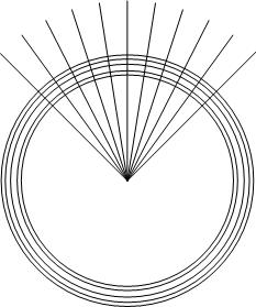
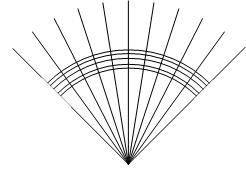
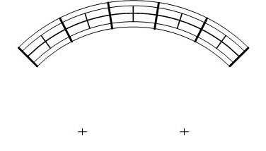
Next I blank out all the concentric circles except that part between the zero and full scale tick mark angle lines. I draw rectangles with no lines and white fill. I then carefully position these to cover up all the circle parts I don't want. I blow the drawing size up to really big when it comes to positioning these cover-up rectangles near the end point angle marker lines. Remember to rotate these rectangles next to the zero and full scale markers to their line angles. Turn the Snap and Glue off to position these precisely. What you end up with is your scale arcs with just the tick mark angle lines.
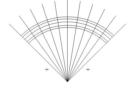
Next I draw a couple of small crosses using two straight lines. Then I Group each cross together into a single entity and using its size and position window place it exactly where I previously measured the mounting holes relative to the rotation axis.
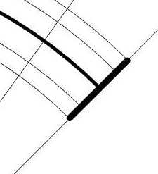
Now we're ready to begin putting in the tick marks. Blow the picture up in size so you are pretty much looking only at the area on the full scale tick mark angle line between the largest and smallest circle. If this position is to receive a major tick mark draw a straight line between the largest and smallest circles on top of the tick mark angle line. Don't worry if it's not at the exact right angle yet. Make this line the line weight you want. Then open up the size and position window on this line you just added and make the angle the same as the angle marker line from the table list. Then you can fine-tune the position of this marker exactly where you want it.
Then do a Copy of this line. Now you can Paste copies of this line to the other major tick marks. Use the size and position window to set the angle exactly; then fine-tune its final position.
In like manner draw a single minor tick mark, set its angle, fine-tune its final position and copy-paste all the other ones using the size and position window to set their angles precisely.
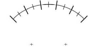
Now erase or delete all those angle marker lines by highlighting them one at a time from beyond the largest circle. Then delete the tick marker start and stop circles. Now what you have left is the new meter scale arcs, tick marks, and the two crosses for the mounting screw holes.
For the lettering use a text block with no line. Do one until you get it how you want it then just copy and paste the others, changing the nomenclature, of course. When you get one text block where you want it, don't forget to change its angle to match its tick mark angle as you place it around the scale arc, again using its size and position window. The little caveat here is that text angles are measured from the vertical whereas arc angles are measured from the right horizontal. You'll need to do a little arithmetic to convert them. Just remember a 0 degree text angle equals a 90 degree arc angle.
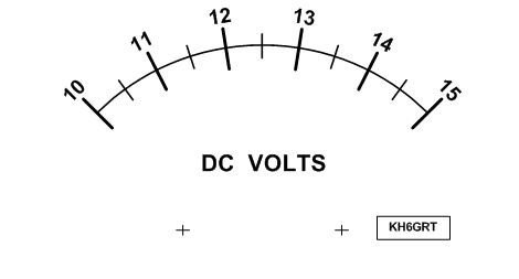
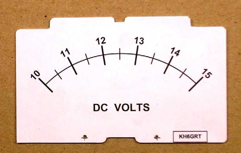
Now print out your new meter scale. I like to use photo paper. either glossy or matte, which gives you a nice print. I use one of those glue sticks to run some adhesive around the edges and center on the back side of the original meter scale. Then while holding the scale in front of a light so you can see something bright through the mounting holes, line up and stick the new meter scale onto the metal back, lining up the small crosshairs with the light through the mounting holes. You have a very short time to make small final adjustments to the position. Rub it down good and put it aside for a couple hours to dry. Then I use a single edge razor blade to nicely trim the paper around the metal scale. What you should end up with is something like this:
 (CLICK ON PICTURE FOR FULL SIZE VIEW)
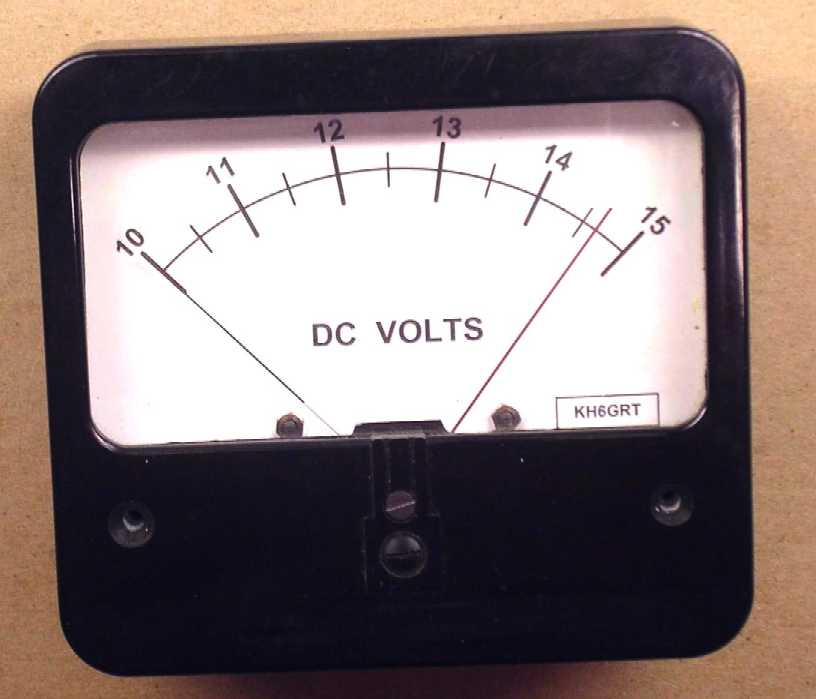
Remounting the new meter scale onto the meter movement and closing up the meter will give you your 'new' meter. The meter I used as an example also has an adjustable red indicator that could be used as a maximum-do-not-exceed or mininum indicator.
 (CLICK ON PICURE FOR FULL SIZE VIEW)
![]()
![]()
![]()