R-390 / R-390A LINE AND CARRIER LEVEL REPLACEMENT METERS
A pictorial of reworking meters for re-use.
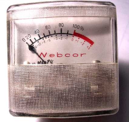
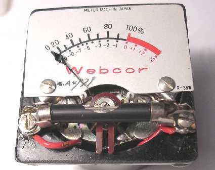
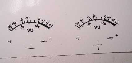
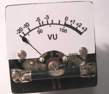
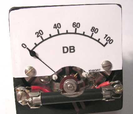
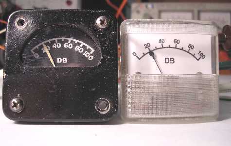
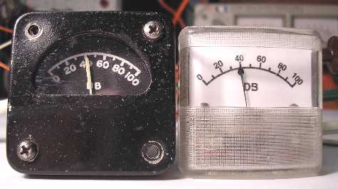
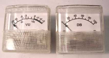
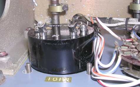
Here's what the unmodified meters looked like. I have no idea what it was originally used in.
The first step was to check the accuracy of the Vu meters. The most accurate ones at the 0 dBm power level were selected to be the line level Vu meters. The others will be modified for use as carrier level meters. These will be individually calibrated later.
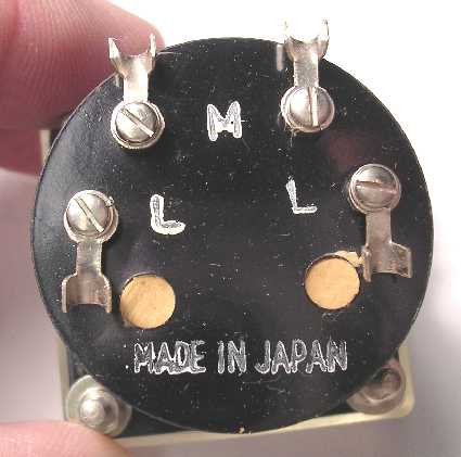
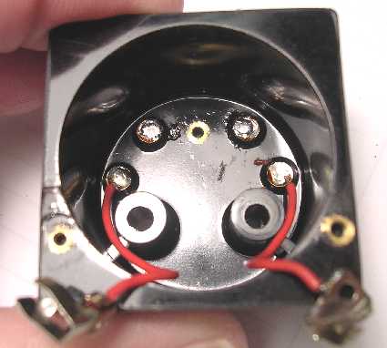
Here's what the rear of the meter looks like. The two terminals by the 'M' are the meter terminals and the two 'L' terminals are for the lamp. The two brown areas are an epoxy-type filler that cover the mounting screws and will need to be scraped out so the meter movement can be removed.
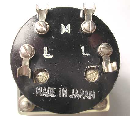
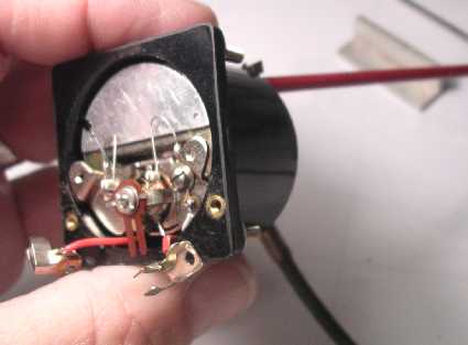
Here the two screws are exposed that hold the meter movement in the case.
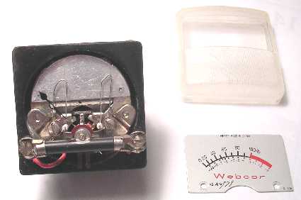
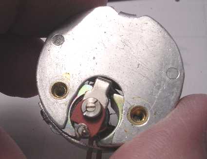
Here's the original meter with the plastic cover removed. The horizontal cylindrical piece with the metal end caps is the internal lamp. The two brown pieces extending downward below that is the mechanical zeroing control.
\
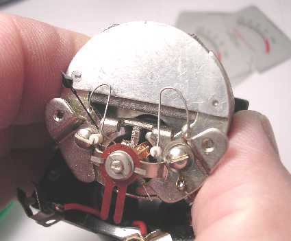
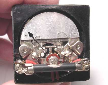
Here's the meter with the plastic cover and the original scale plate removed. Two tiny screws hold the plate to brackets seen just above the lamp's end caps.
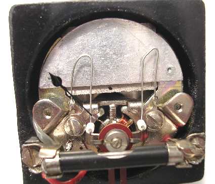
Here's a close-up of the previous picture. This is before any mods were done to the meter.
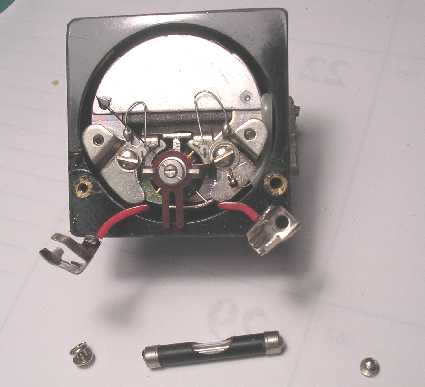
The meter is starting to be disassembled. Here the lamp and lamp clips have been removed.
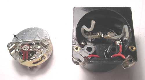
Here we have the meter movement lifted out of the case after the two screws on the back side have been removed.
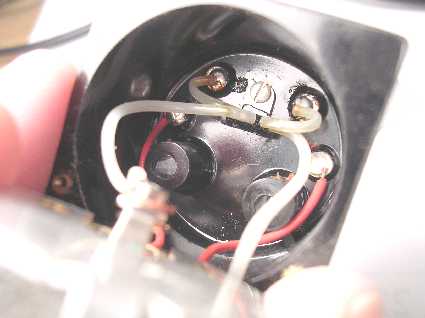
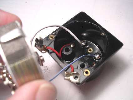
Here's an internal view of the meter case with the meter movement held to the side. The white wires all go to the copper-oxide rectifier mounted to the rear panel. The red leads are for the lamp. The next step will be to unsolder the wires from the meter movement and get rid of that rectifier.
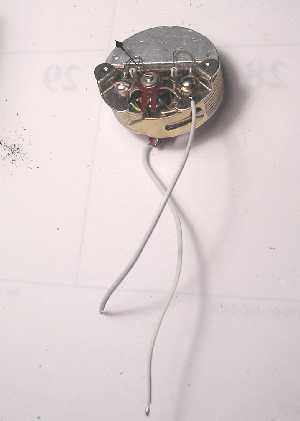
Here's the meter movement disconnected from the rectifier.
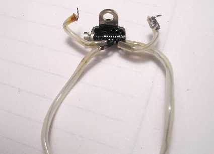
Here's the Vu meter's rectifier removed from the case. Since Vu meters measure AC voltage and D'Arsonval meters are DC measuring devices, a bridge rectifier is used to full wave rectify the AC voltage to a DC voltage which deflects the meter. Since the carrier level meter requires a DC meter, we don't need the rectifier so we get rid of it.
Here's the empty meter case after the rectifier has been removed. The red lamp wires are left alone.
This is a rear view of the meter movement. The electrical connection is at the bottom of the brown insulator. The screw above it controls the tension in the movement bearing while the outer screw locks it in place.
New wires are connected to the meter movement.
The new meter movement wires are soldered to the meter terminals on the rear of the case. This type of work would go a lot easier if you had three hands.
After the meter movement is reseated back into the case and the two rear screws reattached, I check the movement continuity before going further. You have to make sure none of the internal wires are pinched or the movement won't sit properly in the case.
Here's the meter movement reassembled into the case with the lamp and its terminals reassembled.
Here's some of the artwork due to be assembled onto the meters. I do my art work using Visio and print the results on photographic glossy paper using a laser printer.
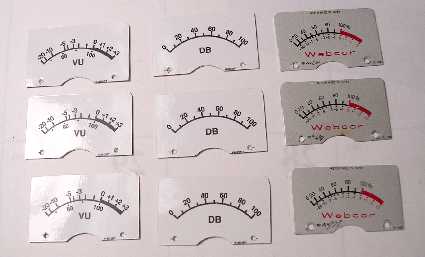
Here's some of the new scales already glued onto the original scales. The paper is carefully trimmed with a razor blade.
Here's a new line level scale attached to a meter.
Here's a new carrier level scale attached to a meter.
Next the DC amplfier printed circuit boards are wired and assembled onto the rear of the meters. Here the electrical zeroing and calibration resistors are being selected. I could have used potientiometers but fixed resistors prevent 'tweekers' from messing things up.
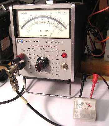
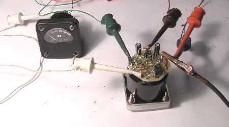
Here we're checking a new meter for accuracy and linearity against an original Carrier Level meter. Both meters are in series, the same current is going thru both meters.
Accuracy and linearity check at 40%.
Accuracy and linearity check at 60%.
Accuracy and linearity check at 80%.
Accuracy and linearity check at full scale. Looking pretty good!
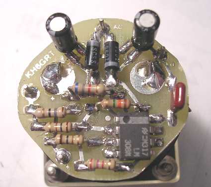
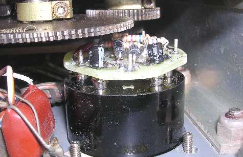
Here's a view of the carrier level meter with its DC amplifier printed circuit board mounted. The two top electrolytic caps standing vertical have been changed to much smaller ones since this picture was made.
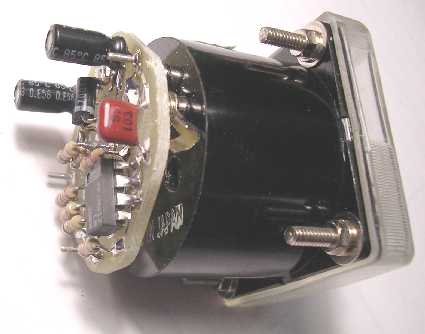
Here's a side view of the carrier level meter with its DC amplifier board installed. Like I said in the previous picture, the two top electrolytic caps standing vertical have been changed to much smaller ones since this picture was made.
Here's a new pair of meters all ready to be installed.
These meters have their mounting screws set slightly less than the original meters. The mounting holes have to be filed towards the large center hole about 0.04" or drilled out with a #15 drill. Here I have elected to drill the holes. The two holes on the right side have been drilled out already while the left ones are still untouched. You can barely see the difference. The larger holes will be completely covered if you install 'original' meters.
Here all four holes have been redrilled with a #15 drill.
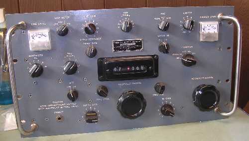
Here we see what my R-390A looks like with these meters installed. Not original but not a couple of empty holes either!
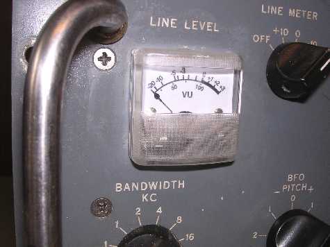
Here's a close up of the line level meter.
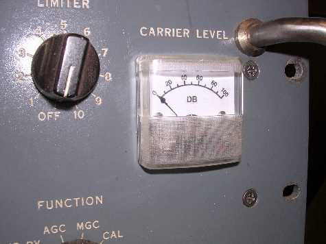
Here's a close up of the carrier level meter.
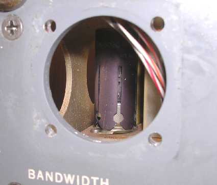
Here's an internal view behind the line level meter.
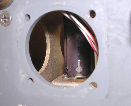
Here's an internal view behind the carrier level meter. There's about a 1/8-1/4" clearance between the DC amplifier printed circuit board and the closest gear. This picture shows the smaller electrolytic caps installed instead of the larger ones in some previous pictures.
Well, that completes our trip....
![]()
![]()