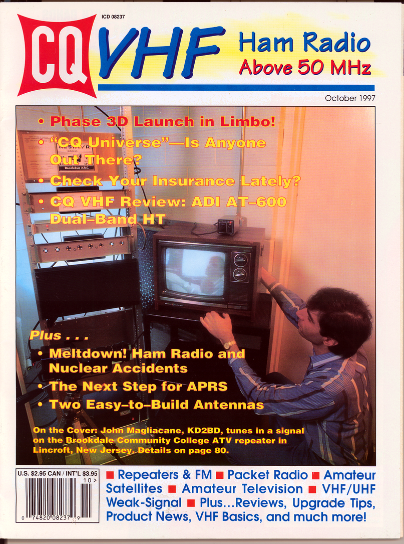
Brookdale ATV Repeater System Information
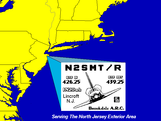
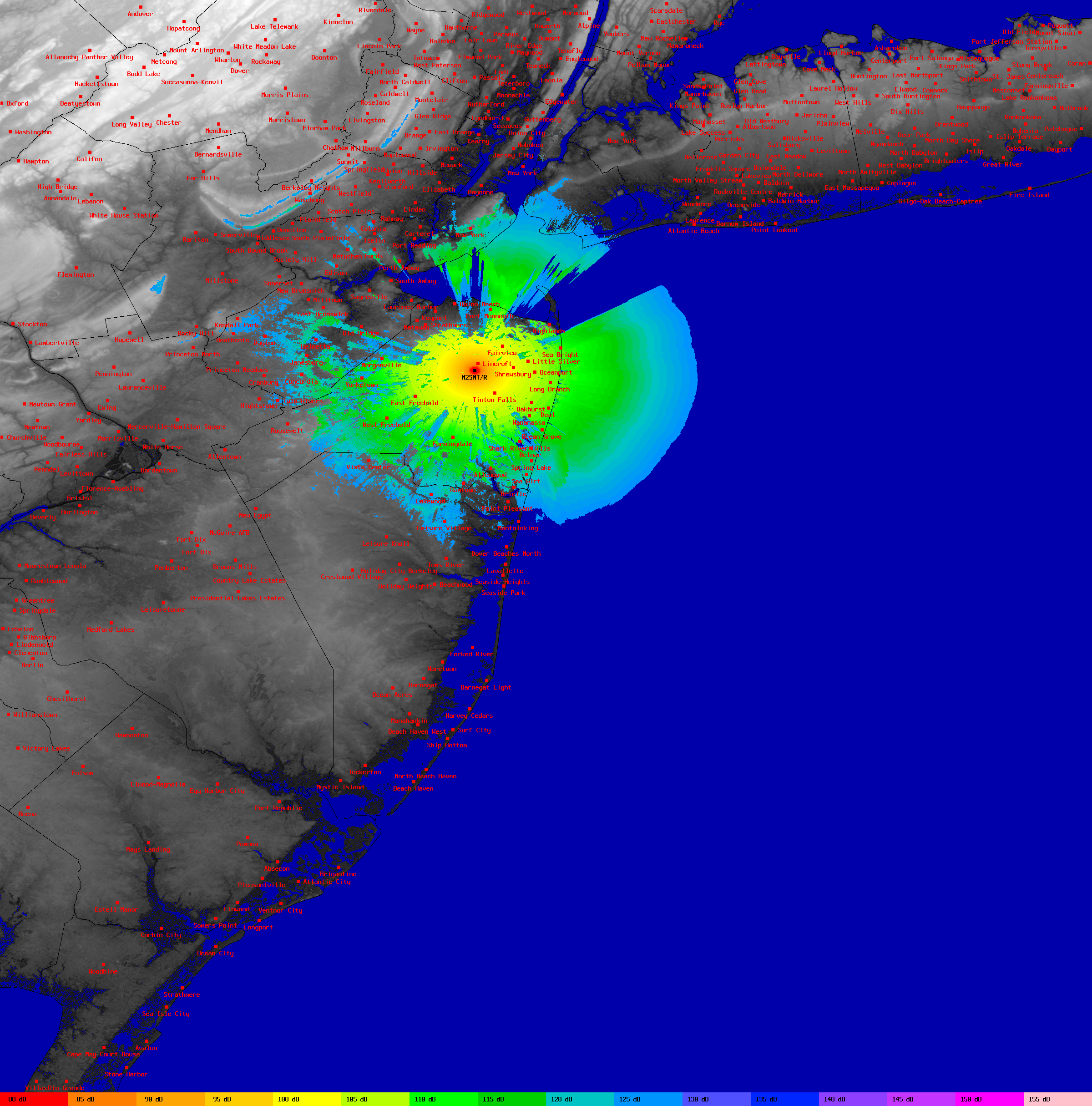
The Brookdale Amateur Television Repeater System was an ambitious project undertaken by members of the Brookdale Amateur Radio Club at Brookdale Community College in Lincroft, (Monmouth County) New Jersey. Conceived in 1991, the repeater became operational on June 14, 1995, and served the North Jersey Exterior Area with an input frequency of 426.250 MHz and an output on 439.250 MHz. The repeater employed a horizontally polarized antenna located 350 feet above ground level, shared tower facilities with radio station WBJB-FM, and was supported by local telecommunications leaders such as Atlantic Coast Communications and Celwave.
The repeater served to:
All of these goals were successfully met.
The Brookdale ATV Repeater System operated with an NTSC video carrier input frequency of 426.250 MHz and a video carrier frequency of 439.250 MHz. The 426.250 MHz input kept all high frequency video sideband components and the FM audio subcarrier of repeater users within the 70-cm Amateur band and 70-cm repeater subband. It also avoided interference both to and from horizontally polarized weak signal operations centered around 432 MHz. A video carrier frequency any lower than this would have caused the lower sideband of the AM video transmission to fall below the 70-cm band edge at 420 MHz. A higher frequency would have caused upper sideband energy to fall within the 431 MHz to 433 MHz subband where weak signal operations currently take place and repeater communications are forbidden by FCC rules.
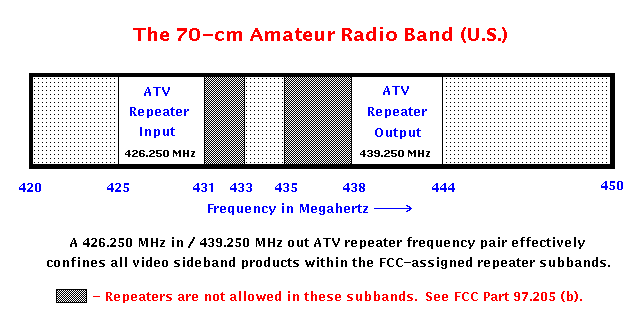
As with the input frequency, the use of 439.250 MHz as a repeater output frequency was a compromise made between conflicting factors that constitute the reality of today's Amateur Radio Service. A VSB-AM Amateur Television emission having a video carrier frequency of 439.250 MHz occupies a 6 MHz bandwidth between 438 MHz and 444 MHz. The use of 439.250 MHz effectively keeps the lower vestigial sideband out of the 435 MHz to 438 MHz International Amateur Satellite subband, while maintaining a substantial (20 dB minimum) degree of isolation to FM voice repeaters and packet radio operations above 440 MHz through the use of horizontal polarization. The interference threat to satellite communications would be very real if DSB-AM were employed on 439.250 MHz as would be the case if this frequency were used as an ATV input frequency. Making matters worse, satellite signals are weak in nature and satellite communication links utilize circular polarization that offers no protection against horizontally polarized ATV signals.
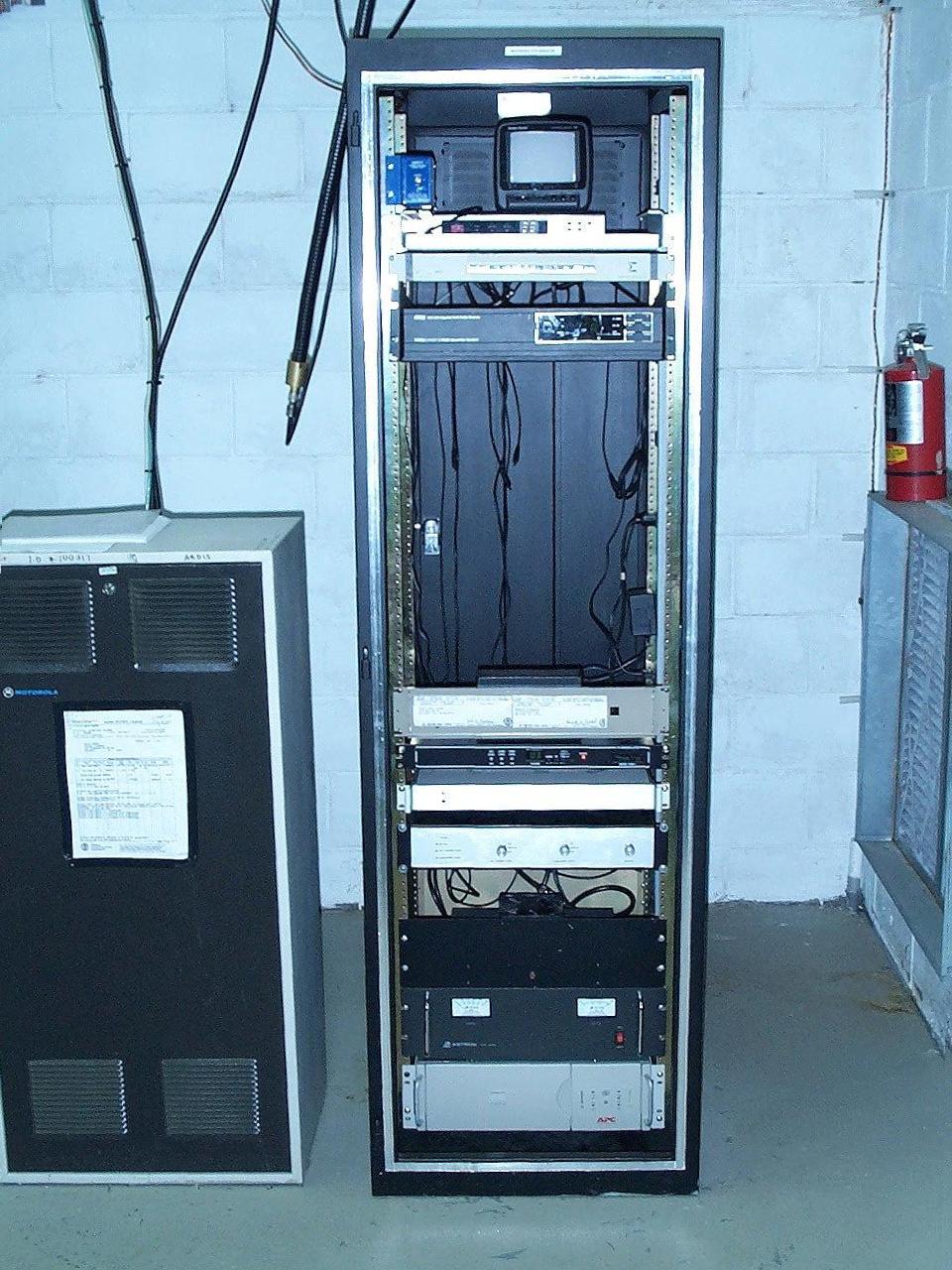
The Brookdale ATV Repeater System was comprised of several sub-systems that were interconnected to form a complete 70-cm in-band repeater system. All sub-systems were contained within a single 19-inch equipment rack.
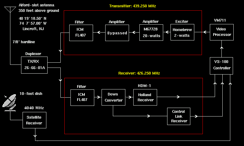
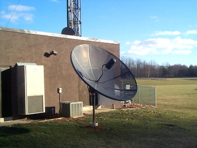
The repeater received incoming NTSC video signals on a video carrier frequency of 426.250 MHz using a horizontally polarized, omni-directional, WB0QCD Alford-Slot antenna system mounted atop a 350 foot radio tower. The antenna was connected to the repeater system electronics through a 390 foot length of Celwave model FLC 78-50J 7/8-inch foam-filled Cellflex hardline. A TX/RX Systems model 26-66-01A combline duplexer allowed both the receiver and transmitter functions of the repeater to share a common feedline and antenna system.
Received signals passed through the duplexer were further filtered through an International Crystal Manufacturing (ICM) model FL407 7-pole interdigital bandpass filter (425 MHz - 431 MHz). The output of the bandpass filter fed a PC Electronics model TVCX-70 crystal controlled GaAsFET downconverter. The downconverter shifted the 426.250 MHz incoming signal to 45.750 MHz (standard USA television receiver IF frequency). A low-noise IF pre-amplifier designed around a Motorola MRF-901 transistor followed the downconverter. The downconverter fed a modified Holland Electronics model HDM-1 television demodulator. The modifications included a direct IF signal input, and a noise-activated audio squelch circuit (KD2BD design). The downconverter also served as the front-end for the control link receiver permitting a single downconverter, antenna, and duplexer to be used for transmitting, receiving, and remote control operations simultaneously. The control link receiver was a homebrew design (based on a Motorola MC3362 chip).
The demodulated audio and video signals from the HDM-1 were then fed into a Micro Computer Concepts model VS-100 microprocessor-based ATV repeater controller/remote video switcher. An Elktronics video I.D. board was added to the controller to permit periodic station identification through the VS-100. Other modifications to the VS-100 included the addition of a high-performance video operated relay circuit.
During periods when a U.S. Space Shuttle was in orbit, regular repeater service was suspended so that video coverage of the shuttle mission could be carried through the repeater system. Such re-transmissions are permitted by the Federal Communications Commission through a special waiver originally requested by the Jet Propulsion Laboratory Amateur Radio Club in 1983. By granting permission to re-transmit Space Shuttle communications on amateur radio frequencies, the Commission recognized amateur radio operators' tremendous interest in space communications, and stated that such re-transmissions:
"afford amateur radio licensees a unique opportunity to become better informed about space communications and to feel a sense of participation in the United States space program. Further, re-transmission of the Space Shuttle communications gives amateur radio operators experience in setting up ad hoc links and networks around the country in order to carry the Shuttle information to interested amateurs. This experience would be invaluable in the event of a natural disaster or emergency in which similar communications links were required."
NASA Television programming carried by the repeater was received via geostationary satellite using a 10-foot dish antenna, a Skyvision C-band LNB, and a Pansat model 2700A MPEG-2 digital satellite receiver. Audio and video from the satellite receiver were fed into the repeater controller for transmission through the repeater system. The last Space Shuttle flight televised by the repeater was the ill-fated STS-107 Columbia mission in early 2003.
The video output from the controller was processed through an FM Systems Model VM711 Video Master Automatic Gain Control System. The VM711 is a baseband video processor that stabilizes video levels, clamps out low frequency interference, and automatically corrects luminance-to-chrominance inequality through a time-gated control system. Processed video available from the VM711 was often of higher quality than those of the ATV signals received by the repeater.
Conditioned video from the VM711 fed a television transmitter consisting of an exciter (KD2BD design) that featured outstanding quality as well as a choice of subcarrier and/or on-carrier audio transmission methods. The 2-watt RF output from the exciter fed a Pauldon Associates intermediate power amplifier designed around a Mitsubishi M67728 55-watt RF power module operating at half power. The output of this amplifier was used to drive a Teletec 150-watt linear power amplifier to full rated output power. The Teletec amplifier then fed a vestigial sideband filter consisting of another ICM model FL407 7-pole interdigital bandpass filter (438 - 444 MHz), and the TX/RX Systems duplexer before feeding the hardline and antenna system.
An Astron 13.8 volt, 50 amp regulated DC power supply, a color video monitor, 439.250 MHz on-air receiver, and video switcher rounded out the major components of the repeater system.
|
|
John Magliacane |
