(This article appeared in the Spring 2000 issue of Amateur Television Quarterly
magazine.)
One of the worst approaches to video sync detection has been the design used by the Micro Computer Concepts VS-100 ATV Repeater Controller. This controller couples baseband video directly into an LM567 PLL tone decoder tuned to the video horizontal sync frequency. This approach suffers from a number of shortcomings. First, the LM567 processes all input signals through a limiter circuit. Due to the capture effect, only the strongest component of the baseband video signal fed to the LM567 will make it through the limiter and be processed by the PLL's phase detectors. If the video signal has a high signal-to-noise ratio, and the strongest video component happens to be around 15,734 Hz (for NTSC video), the PLL will reliably detect the presence of the video signal. However, the strongest video component that makes it past the limiter is not always something related to the horizonal sweep rate of the video signal. Depending on picture content, there may be a more substantial component at lower frequencies, such as the vertical sweep rate, and when this happens, the video operated relay fails to reliably detect the presence of the video signal.
Some VOR designs place a 15,734 Hz active bandpass filter ahead of the LM567 so that the PLL only sees video components related to the horizonal repetition rate of the video signal. This significantly enhances the reliability and the sensitivity of the VOR, but there's still another problem. The PLL requires an input signal that is continuous in phase. Since NTSC, PAL, and SECAM video all have vertical sync intervals containing equalizing pulses at twice the horizontal sweep rate, any PLL tuned to the horizonal sweep frequency of the video signal will break out of lock at the video field rate. If the PLL is constantly breaking in and out of lock, it cannot be reliable. A better approach is needed.
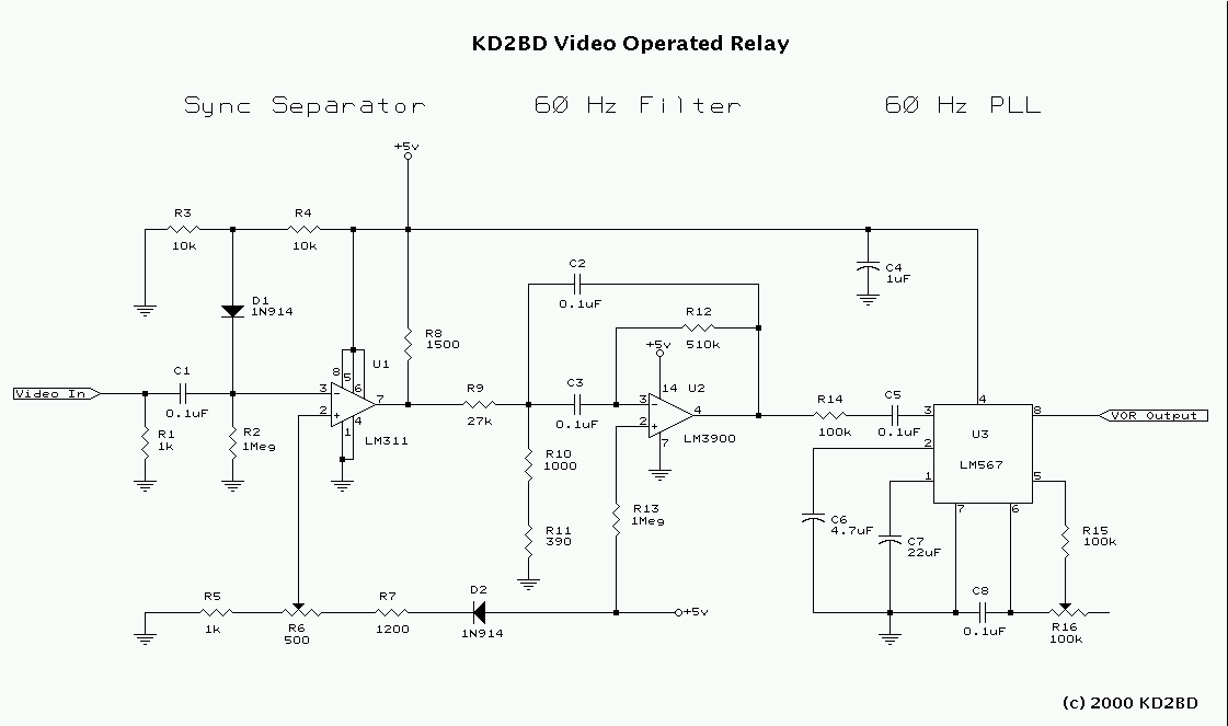
After much thought, testing, and research, I came up with a different approach to video sync detection. The result of my work is shown in Figure 1. In operation, video signals are clamped to a constant voltage level through capacitor C1, diode D1, and associated resistors R3 and R4. They are then fed into an LM311 voltage comparator that performs the duties of a video sync separator. The purpose of the sync separator is to strip the sync pulses from the video waveform, thereby providing a constant output voltage regardless of the content or the peak-to-peak voltage of the video signal. The extracted sync pulses are then passed along to an active bandpass filter designed around an LM3900 operational amplifier. This filter has a center frequency of 60 Hz, a gain of 10, a Q of 10, and a 3 dB bandwidth of only 6 Hz. Its purpose is to extract only the vertical component of the video sync, which unlike the horizonal component, is phase continuous with interlaced video. The sinusoidal output of the filter is then passed along to an LM567 PLL tone decoder tuned to the vertical sync rate (60 Hz) of the video signal. An open-collector, active low output is available for interfacing with external circuitry.
Some of the advantages this design holds over others include:
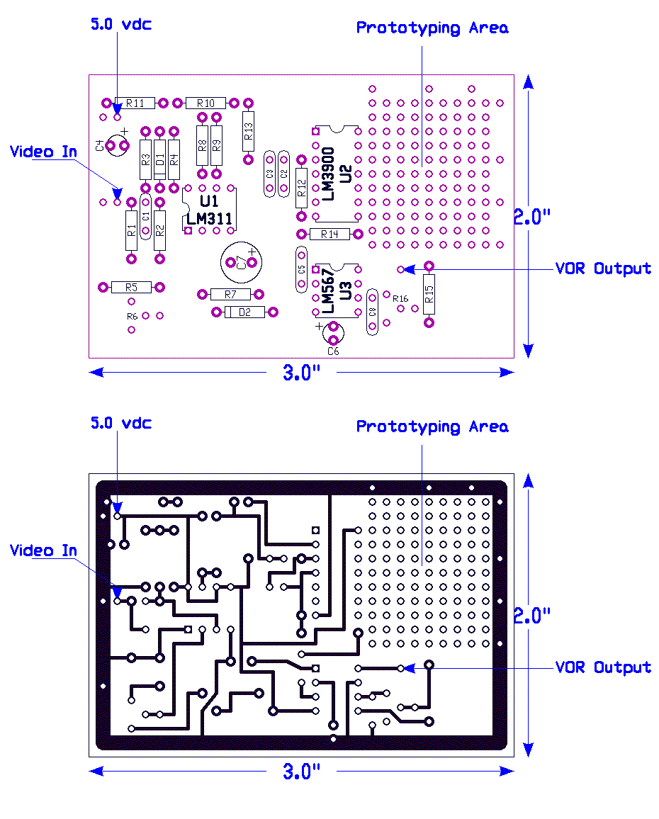
The KD2BD Video Operated Relay was constructed on a small perforated circuit board using point-to-point wiring techniques. David Sudduth, KB0ZNP, has developed PC board and layout drawings for this project. In operation, potentiometer R6 is adjusted so that the output of the LM311 voltage comparator provides clean sync pulses with a noise-free input signal. R16 is adjusted midway between the points where the PLL goes out of lock. Lock may be determined by tying a 330 ohm resistor and LED between the +5 volt supply and the VOR Output. Capacitor C7 controls the reaction time of the VOR. Any value between 10 uF and 47 uF will work well, although the higher values within that range are perferred to avoid rapid triggering on very weak and noisy signals.
The KD2BD Video Operated Relay represents a slightly different approach to video sync detection, and one that has demonstrated higher reliability than other popular approaches that rely on the presence or absence of energy at the horizontal repetition rate of the video signal.
Anyone may duplicate and use this circuit design provided it is for non-profit uses only.
|
|
John Magliacane |
