80 METERS
L1 = 36 turns #24 AWG enam. on 1-inch dia.
     form, close-wound. Tap 15-3/4 turns
     from C1 end.

L2 = 6 turns #24 AWG enam. close-wound
     over cold end of L1.

L3 = 36 turns #24 AWG enam. close-wound
     on 1-inch dia. form. Tap 12 turns
     from cold end.

L4 = 5 turns #24 AWG enam. close-wound
     over cold end of L3.
|
40 METERS
L1 = 18 turns #20 AWG enam. on 1-inch dia.
     form, close-wound. Tap 5-3/4 turns
     from C1 end.

L2 = 4 turns #20 AWG enam. close-wound
     over cold end of L1.

L3 = 18 turns #20 AWG enam. close-wound
     on 1-inch dia. form. Tap 6 turns
     from cold end.

L4 = 4 turns #20 AWG enam. close-wound
     over cold end of L3.
|
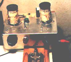
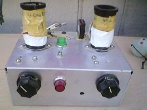
 Construction:
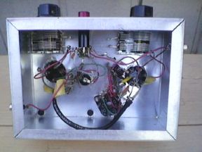