 amateur radio license
required to operate on the air!
amateur radio license
required to operate on the air!
500mW CW TRANSMITTER
Cost estimate: $15
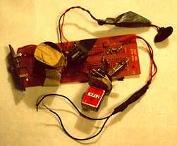
A very quick and easy way to get on the air is to build a "Michigan Mighty Mite" CW transmitter for 160, 80, 40 or 30 meters originated by Ed Knoll, W3FQJ and developed by Tom Jurgens, KY8I. It can't get simpler than this! I made my very first QSOs with a 40-meter version (photo). It has very few parts, costs almost nothing, and it works!
Output power is about 500 milliwatts with a 12-volt power supply. To operate, attach 50-ohm dummy load or appropriate 50-ohm antenna (do yourself a favor and use a half-wave dipole antenna to avoid tuners and assure good results) and ground, insert crystal and close the key. Adjust the variable capacitor for the cleanest signal that has the most power (compromise).That's it! You're on the air, and can confirm that it's working with field strength meter. Power output can be figured with a common multitester by using a very simple wattmeter circuit.
Another way to check if working is to hook up a small incandescent lamp
across the antenna terminals: if it lights, the transmitter works. I use a 7.5V 0.22A bulb
which is a 1.65W lamp [Watts = Volts X Amps].
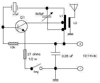
Q1:
2N2222, SK3265 or similar very inexpensive general-purpose NPN transistor. I use a plastic-case transistor that came in a bargain-pack from Radio Shack - works fine. Use heat sink - try an alligator clip if you don't have a heat sink handy.
TANK COIL:
use a 1.25" diameter form (35mm film canister, pill bottle, etc.) and #20 - #22 AWG enameled ("magnet") wire. To make tap, wind L1 to the "tapped at" number of turns (see table below). Make a loop about 1 inch long, twist it a few times and finish winding. Sand the insulation off the end of the loop. This is your tap. After winding L1, wrap it with a thin layer of masking tape and wind L2 on the tape, on top of and in the same direction as L1. Secure L2 with more tape and finish by sanding insulation off remaining leads.
            L1:                               L2:

(primary/collector windings)         (secondary/antenna windings)
160m--60 turns, tapped at 20         160m-- 8 turns
 80m--45 turns, tapped at 15          80m---6 turns
 40m--21 turns, tapped at 7           40m---4 turns
 30m--15 turns, tapped at 6           30m---4 turns
XTAL: fundamental-mode crystal for desired frequency.
About that variable capacitor - the unit in the photo is a discontinued item from Radio Shack, but NO PROBLEM - salvage one from an old transistor AM Radio or try a trimmer capacitor. Of course, a fullsize variable will work - but it will also be bigger than the rest of the transmitter! Tracking down variable capacitors at a good price is a noble challenge and part of the game.
NOTE: a "Super Mite" 1-watt version of this transmitter using an 18-volt power supply (such as two 9V batteries) can be built by using a 2N3053 for the transistor with heat sink and substituting a 2.7-ohm 1/2 watt resistor for the 27-ohm 1/2 watt resistor AND also substituting a 0.01uF 100V capacitor for the 0.05uF capacitor. (CQ, Aug 2004, p.71)
..need parts?...
Source:
Ingram, Dave, K4TWJ, "World of Ideas: QRP Fun - Part II"
                     (CQ, Vol.48, No.3, March 1992, pp.107-108)
WHAT NEXT?-- Try the Station Controller
that frees you from switching the antenna from transmitter to receiver and back again.
It is simple and provides full-QSK operation and electronic keying.To make it work
with the transmitter described above, just short the transmitter's key terminals --
keying is then provided by the controller via the +V input.
***HOME***