|
Henry Radio 5K Classic Amplifier
|
|
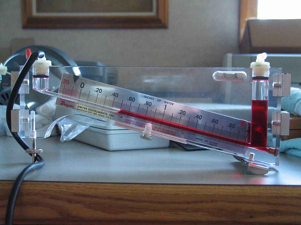 |
 It's
all about the tools! Here's a picture of the
Dwyer Series 102.5 manometer I used for all of the before and after
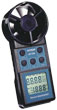
static pressure measurements. I also used a Greenlee
handheld vane anemometer with integrated
temperature sensor to directly measure the airflow, in CFM, at the exhaust
point above each tube. I purchased these tools on Ebay at prices far
below retail or wholesale. It's
all about the tools! Here's a picture of the
Dwyer Series 102.5 manometer I used for all of the before and after
static pressure measurements. I also used a Greenlee
handheld vane anemometer with integrated
temperature sensor to directly measure the airflow, in CFM, at the exhaust
point above each tube. I purchased these tools on Ebay at prices far
below retail or wholesale. |
 |
Back cover removed showing the power supplies upper deck and the original Dayton 2C915A (220vac -- 140cfm blower) mounted to the underside of the cabinet. The RF deck enclosure was removed. |
 |
Upper deck of the power supply with the original blower removed. From left to right you can see the Filament transformer, HV filter cap in the rear, Bleeder resistors (back right) and the Relay/Control circuit transformer (front right). |
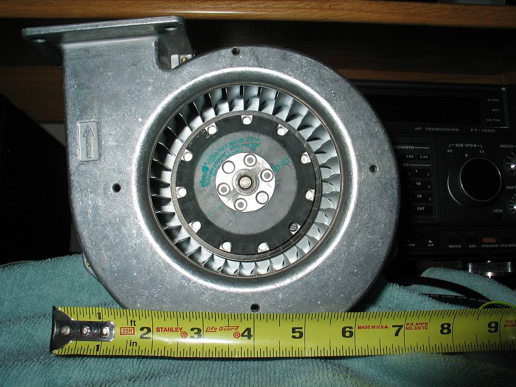 |
After a great deal of research and measuring, I chose a EBM G2E120-AR38-43 (click link for catalog -- 1MB PDF file -- see page 19) blower as a replacement for the Dayton. The new blower uses a split capacitor motor which is much easier to speed control by using a capacitor in series with one of the motor leads. Another advantage is the 'External Rotor' design which places the motor in the center of the squirrel cage. The motor runs very cool. |
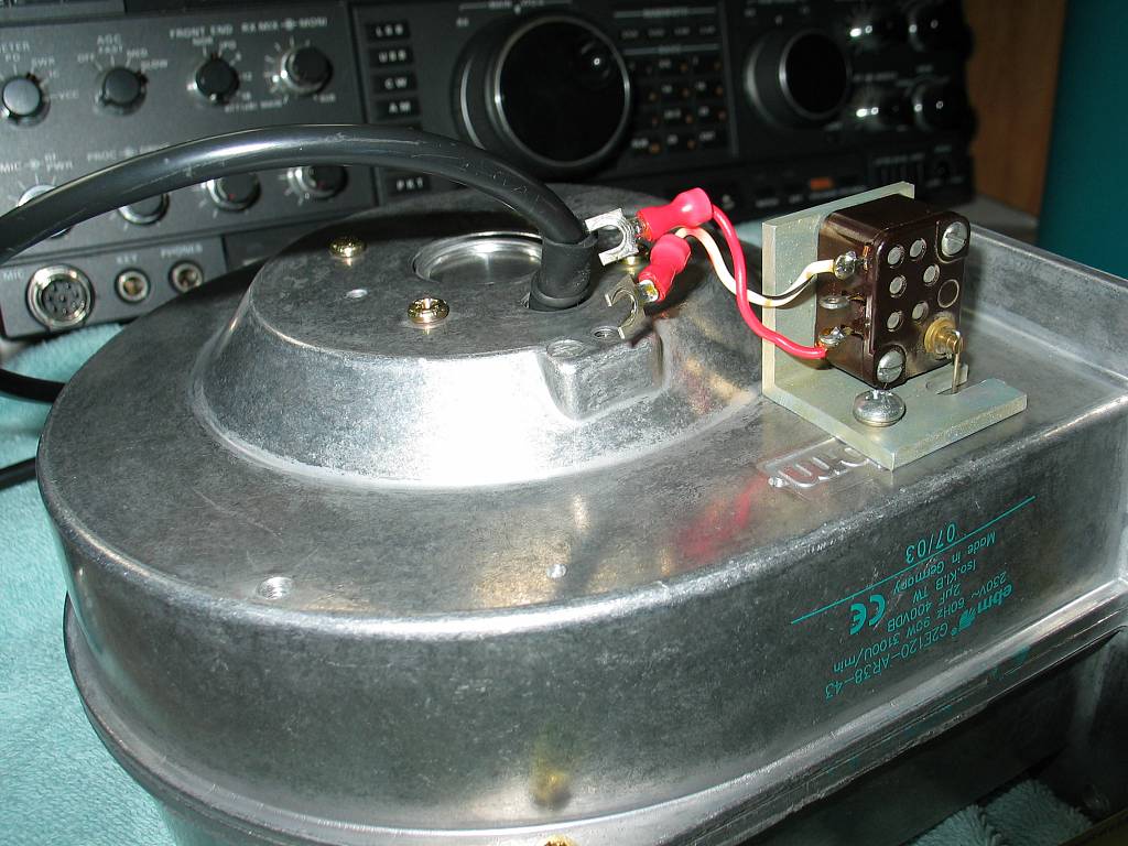 |
The EBM blower has a cast aluminum housing and zero maintenance ball-bearings in the motor. This picture shows the air switch mounted. Henry uses an air switch to turn on the tube filaments and relay power supply only when sufficient airflow is present to cool the tubes. |
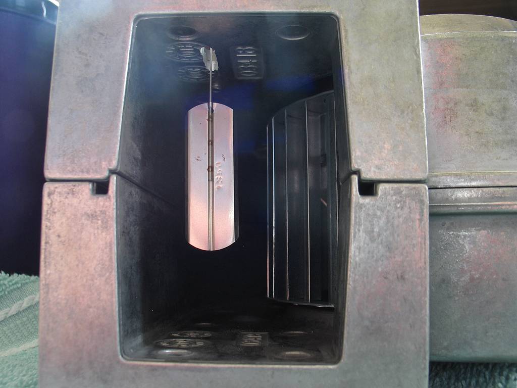 |
Airflow Switch End view showing the air vane attached to the air switch. The new blower has a much wider squirrel cage which allows it to move more air at a slower, quieter speed than the original Dayton blower. |
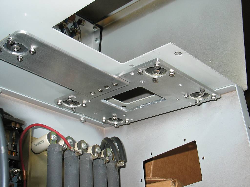 |
After dealing with all of the vibration problems of the original blower, I decided not to take any chances with the new one. After more research I found a company that makes small Anti-vibration Mounts (Part # 62490-2) that were perfect for my application. Brad, K7ZSD, made the mounting plate for the new blower out of 3/16" aluminum plate. After further experimenting, it became obvious that an extension arm on the plate would be necessary to properly distribute the weight of the fan. |
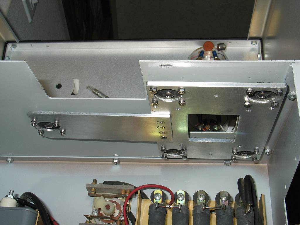 |
Here's a side view of the new blower mount. Each anti-vibe mount is attached to the plate with four 4-40 screws. The entire plate is attached to the amplifier chassis with 8-32 screws and Ny-Lock nuts. The screws run through the center brass bushing in each anti-vibe mount. LockTite was used on the 4-40 hardware. |
_01_large.jpg) |
The new blower installed. I used a hollow foam weather stripping gasket to fill the gap between the top of the blower mounting plate and the underside of the chassis. The gasket material is shaped like the letter 'D' with an adhesive on the flat side of the 'D'. The hollow portion minimizes any vibration transfer between the plate and the chassis. At the top center of this picture you can see the HV, Filament and Control plugs protruding from the bottom of the RF deck. |
_05_large.jpg) |
Here you can see the blower with it's starting capacitor and terminal strip mounted. The original blower also had the same terminal strip mounted on it. The HV, Filament and Control cables have been plugged into the RF deck. That completes the blower installation. The next step will be the necessary modifications to the RF deck to allow more efficient airflow from the blower through the tube anodes. |
| RF Deck Modifications | |
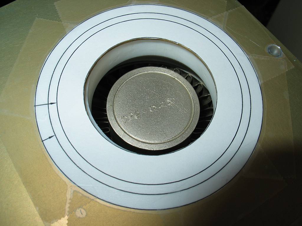 |
The original exhaust hole above each of the 3CX1200A7s. The top of the tubes anode is visible at the center of the image. You can also see the white Teflon chimney which sits on the top of each tube. I made paper templates (drawn in AutoCAD) to facilitate the required enlargement of each hole. The original hole was filed out to the first line on the template. The second line represents the tube anodes outside diameter. The outside line represents the outside diameter of the new chimneys. |
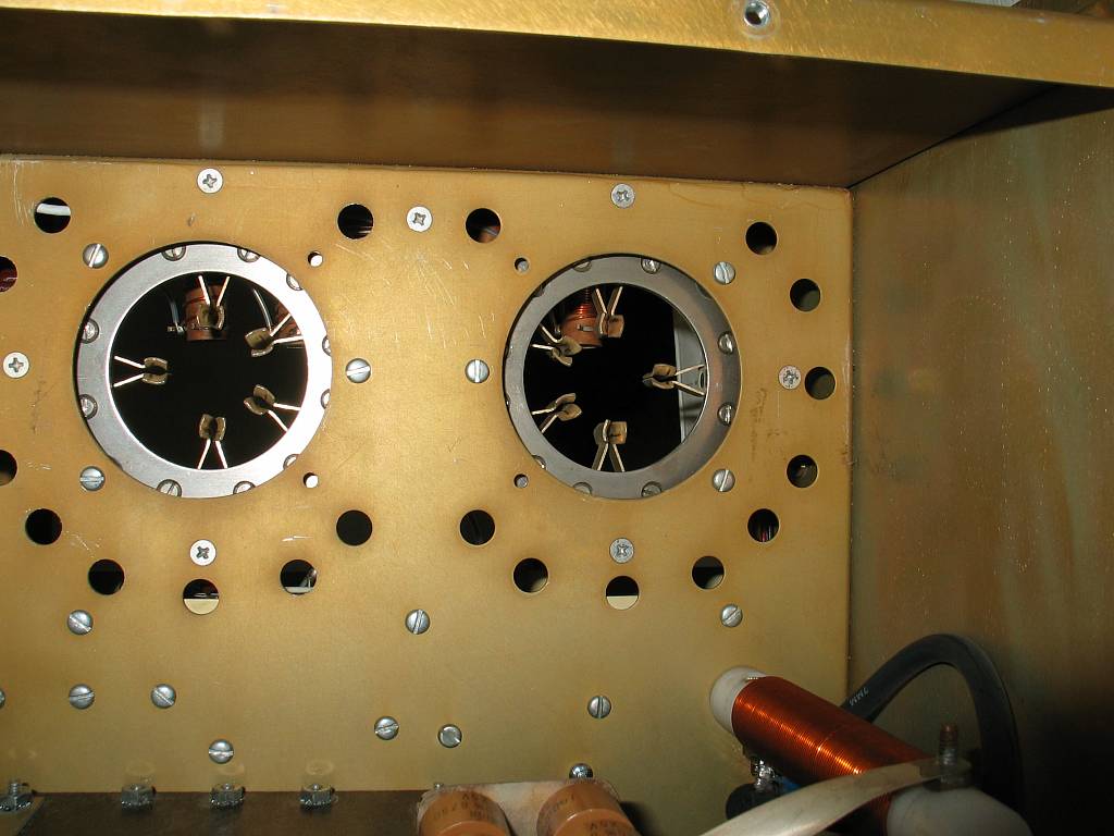 |
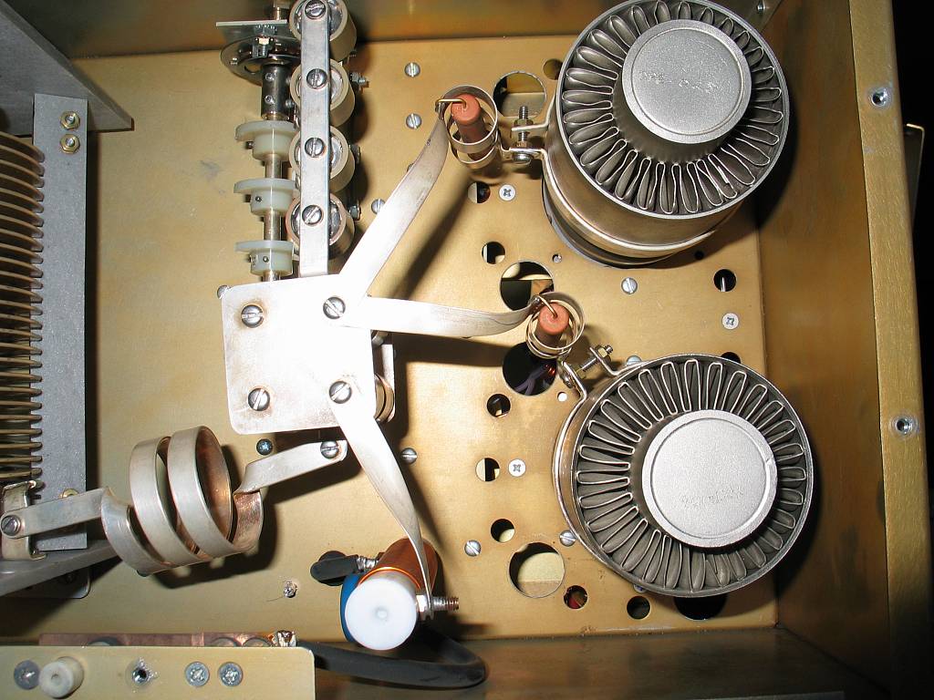
Looking down on the tube sockets with the top cover of the RF deck and the tubes removed. Notice the smaller holes arrayed around each socket. The majority of the air from the blower is expected to go through these 3/8" diameter holes. After extensive airflow and static pressure measurement, I determined that there really needed to be about three times as many holes to allow the air to pass unrestricted from the underside of the chassis into the main pressurized compartment of the RF deck. |
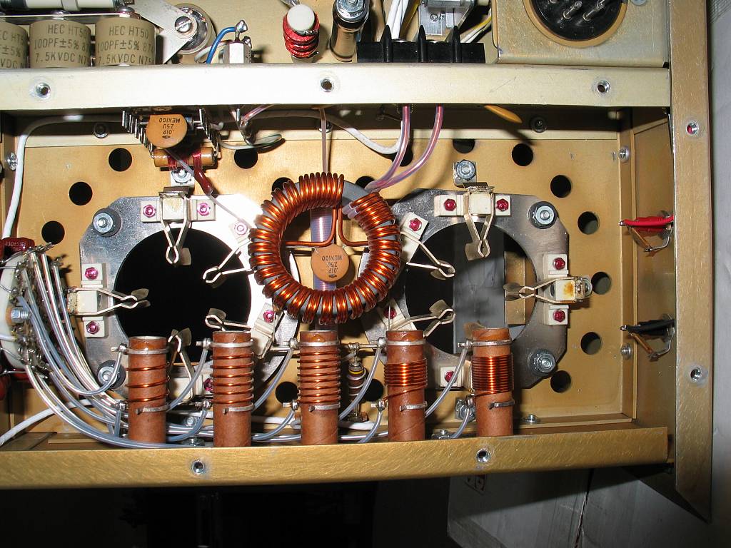 |
Here's what the tube sockets look like from the bottom (the bottom cover of the RF deck having been removed). The filament choke is in the center and the tuned input coils are at bottom center. Before modification, the static pressure below the tubes was over 1" SP when the pressure in the upper chamber of the RF deck was .5" SP. It was obvious that some of the 3/8" holes would have to be enlarged. |
 |
A Greenlee 1/2" conduit knockout cutter was used to enlarge 6 of the 3/8" holes to 7/8" diameter. There are now three of the larger holes around each tubes base. The static pressure below the sockets now measures .7" SP and .55" SP above. The blower can now be run at a much slower speed while still providing the required airflow. |
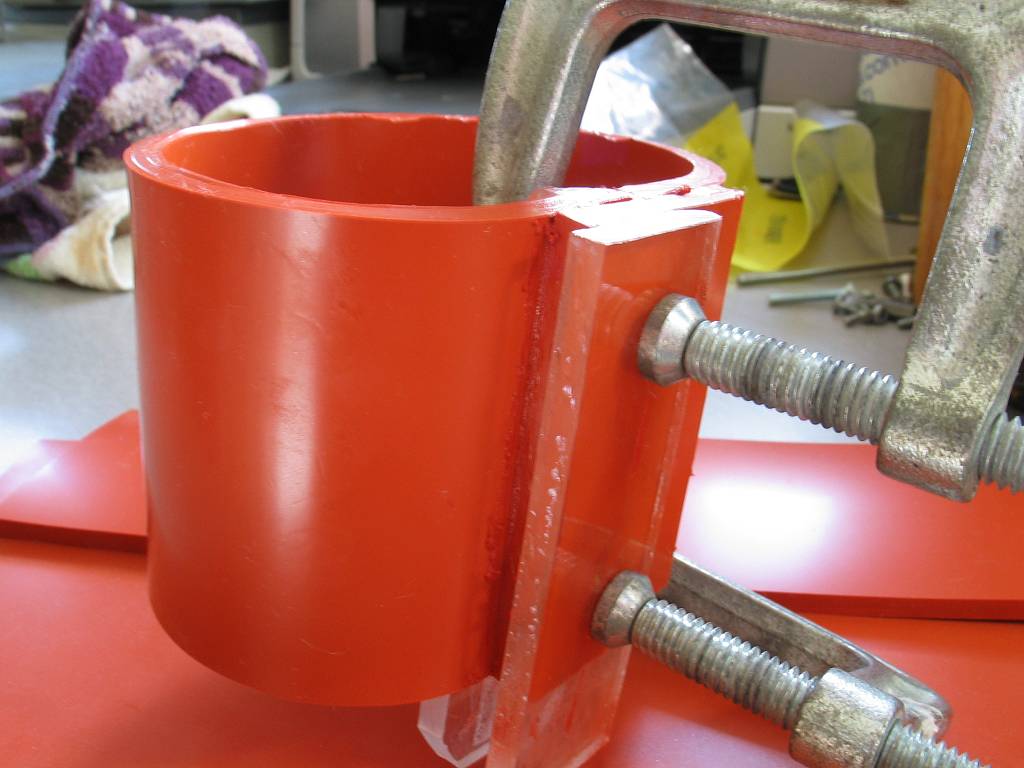 |
After enlarging the exhaust holes in the top cover of the RF deck, it became necessary to make new chimneys. I used the same high temp silicone rubber (500 deg F) that Alpha uses for their chimneys. The rubber is 3/16" thick, 50A Durometer, purchased from McMaster-Carr in a 12" x 12" sheet (Part# 8632K35 -- Catalog page 3285 -- Cost $25.00). Dow Corning 736 High-Temp RTV was used to glue the chimneys (Part# 74515A32 -- Catalog page 3177 -- Cost $7). |
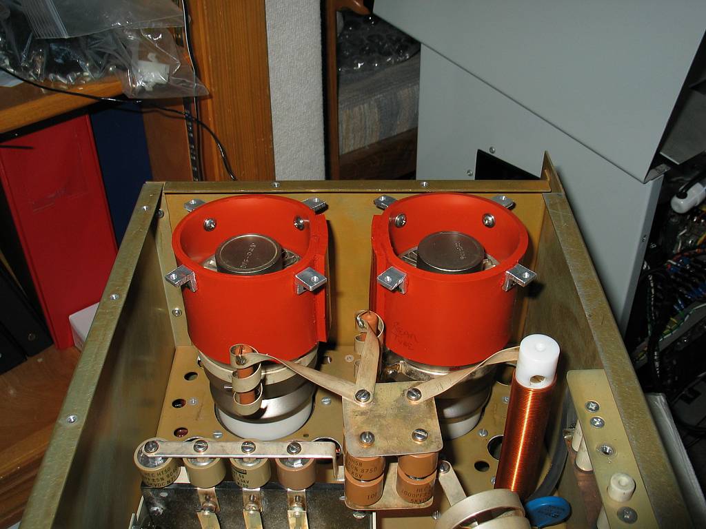 |
New chimneys sitting on the tubes. Also notice the aluminum angle brackets attached to each chimney. The brackets were made from 1/2" aluminum angle, then drilled and tapped for 6-32 screws. The chimneys are held tightly against the underside of the cover with screws from the top. This mounting method creates a good seal between the top of each chimney and the underside of the RF decks cover. All of the air is being forced through the tubes anodes. |
 |
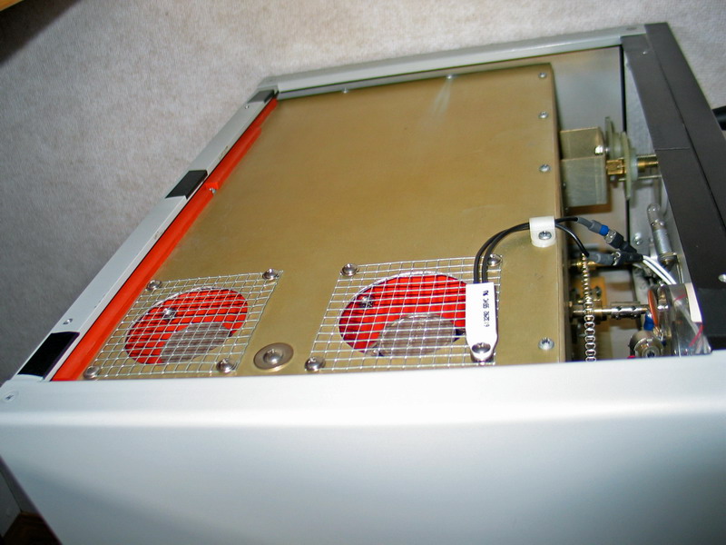
Finished! The chimneys installed, cover screens in place and screws to hold everything together. |
 |
If you compare this picture to the pre-modification one with the paper template, you'll get a good idea how much the airflow was restricted with the original chimneys and exhaust holes in the RF deck. |
|
|
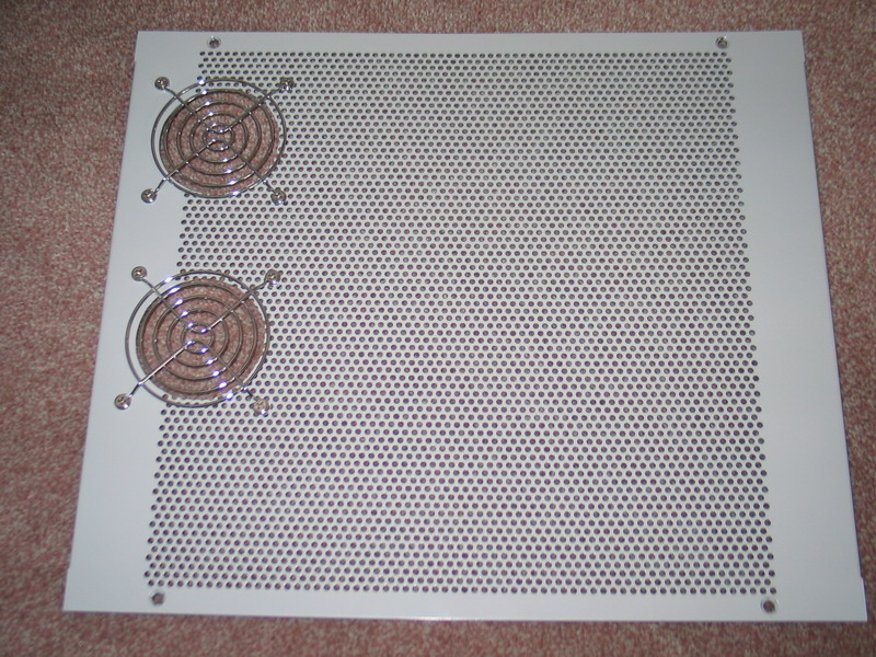
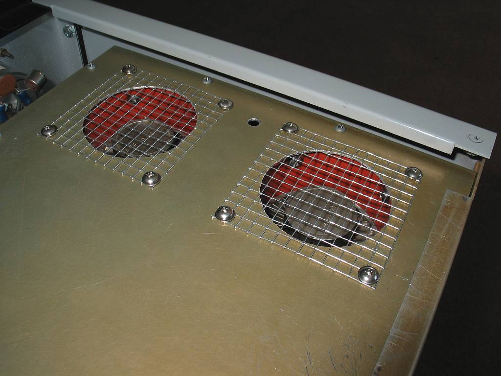
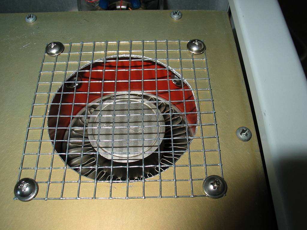
Another flaw in the original design of the Henry was the top cover of the amp pedestal. Henry uses a perforated aluminum cover which gets very hot because the hot air from the tubes has to be diffused through it rather than being exhausted straight out of the cabinet. When I used the amp for contesting, it was always necessary to remove the outer cover for more efficient cooling. I punched large holes directly above each tube and put the chrome fan guards over each to create a more finished look. |
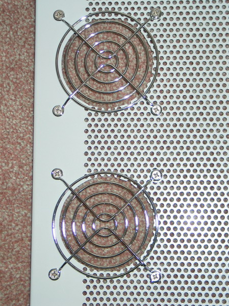 |
Close-up of the new chrome
guards. Now all of the hot air exhausts straight out of the RF deck. The top of the amps cabinet stays cool to the touch even when running high duty modes like RTTY. |
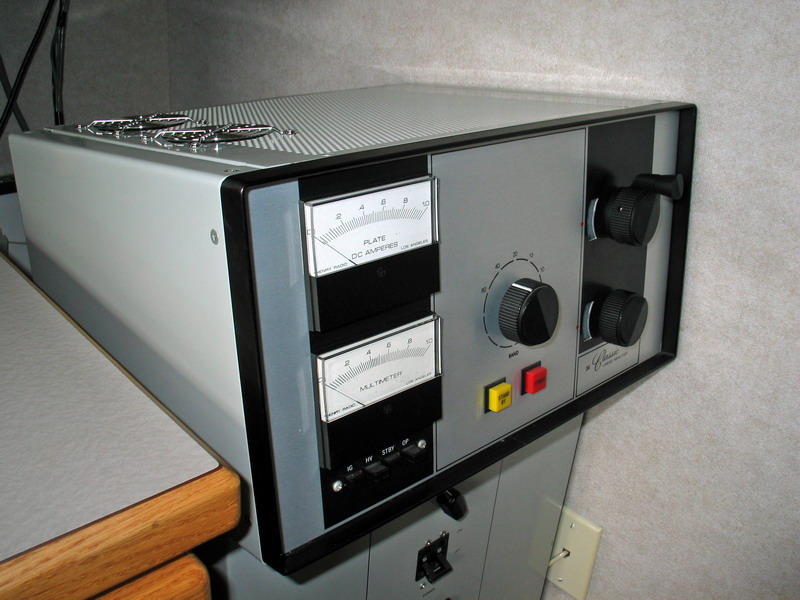 |
All done! Completed project with the top cover re-installed. |
|
Blower Speed Control System |
|
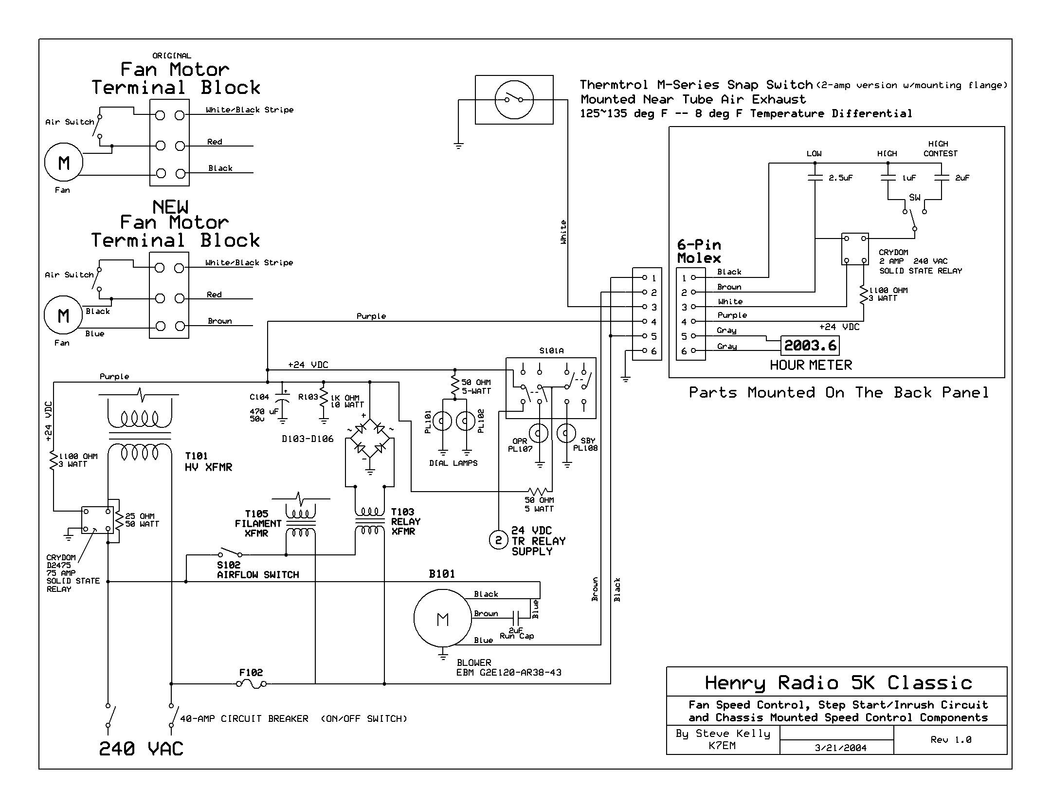 |
Here's my schematic showing the incorporation of the new blower, the complete speed control circuit, including the three additional capacitors which allow the blower to be run on 'Low', 'High' and 'Contest High' speeds and the Step-Start components. I copied the basic power supply from the Henry manual and then added my new mods to it. This schematic was drawn with Express PCB and Schematic software -- It's FreeWare. CLICK HERE to download my actual ExpressSCH drawing file. |
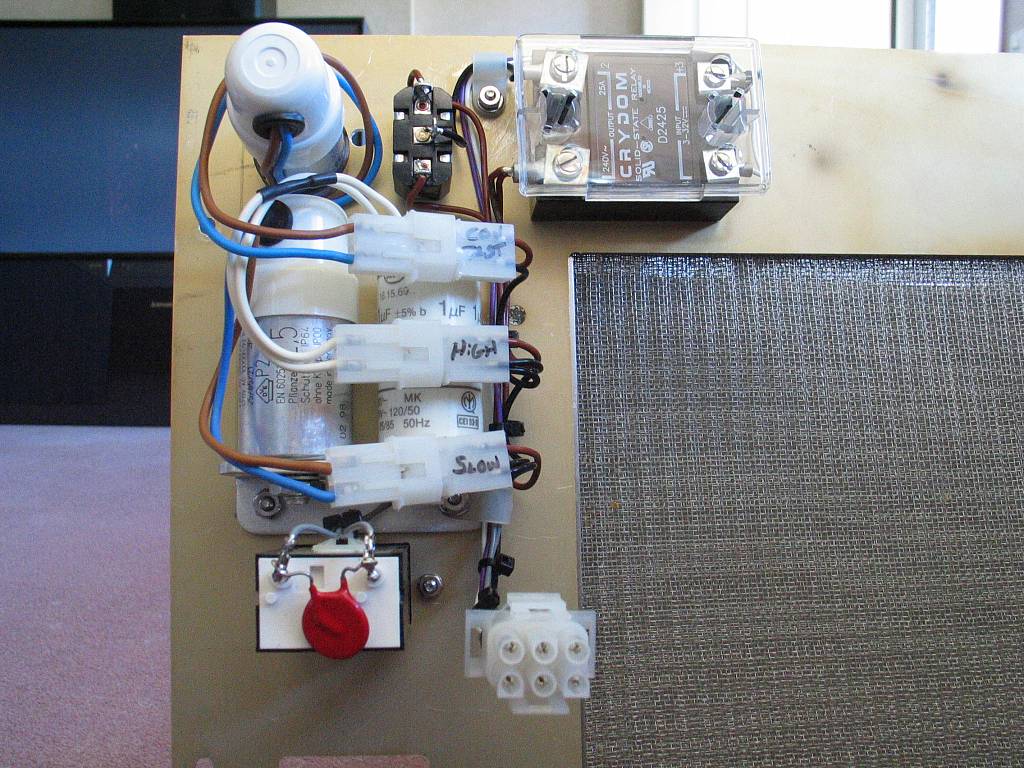 |
With the exception of the temperature sensor (Thermtrol Snap-Switch) all of the speed control parts are mounted on the inside of the amps back cover. The three capacitors connect to the circuit with 2-pin Molex plugs and sockets. The SPDT toggle switch sets the high speed for either 'High' or 'Contest High'. When the snap-switch closes, the Crydom SS relay is energized which in turn adds the additional capacitance in series with one of the motor leads causing the motor to speed up. |
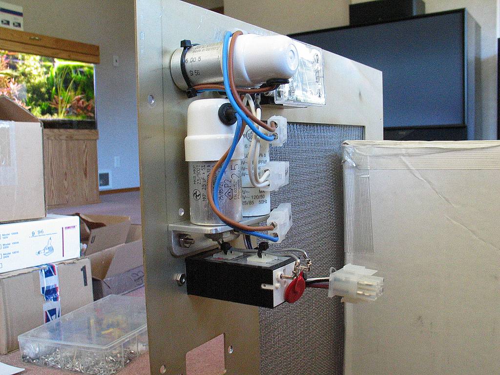 |
This side view of the speed control components shows the capacitors on their right angle mounting bracket and the amps runtime hour meter. You can also see the 6-pin Molex connector I used to connect all of these components to the main wiring inside the power supply compartment. |
 |
The outside of the back panel showing the toggle switch and the hour meter. I installed the hour meter in 1988. |
|
|
Thermtrol snap switch mounted in the air exhaust stream. When the air exhaust temp reaches 130 deg F this bi-metal switch closes which causes the SS relay in the fan speed control circuit to energize. The SS relay adds additional capacitance in one of the blowers motor leads which makes the blower run faster. |
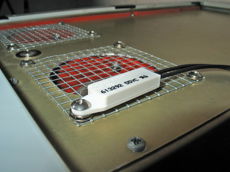 |
Close-up view of the Thermtrol snap switch. |