|
Download the 5K Classic Owner's Manual

 |
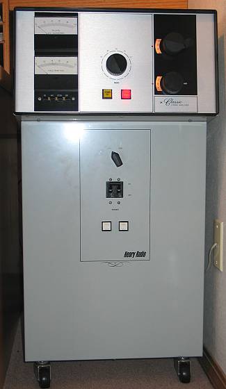
The Henry Radio 5K Classic amplifier has continuous coverage
from 80 thru 10 meters using a pair of Eimac 3CX1200A7s in grounded grid.
The power supply is capable of 4,000 vdc @ 1.5 amps in intermittent service.
Continuous duty is 4,000 vdc @ 800 mA. The power supply components and
blower are located in the lower part of the pedestal. The RF deck is in
its own self-enclosed and shielded enclosure that slides into the upper part of
the pedestal. The high voltage, filament and control connections are made
via umbilical cords to the underside of the RF deck.
I purchased this amplifier new from Henry Radio back in 1988 and have always
been disappointed with the excessive blower noise caused by the poorly built
Dayton 2C915 (140cfm) blower. First, mechanical noise was caused by induced low
frequency vibrations in the cabinet from an out of balance squirrel cage (Dayton
blowers are notorious for being poorly balanced). Second, was the severe
airflow restriction caused by the holes around the tube bases and the exhaust
holes in the top of the cabinet being too small. The measured airflow at
the exhaust holes was only 25cfm (per tube) with the blower capable of more than
twice that level. So, after 15 years, I finally decided to do something
about it. (See Cooling System Upgrade) |
The second thing I never really liked was the TR relay
system. Henry did use a Jennings RJ2B vacuum relay for 'RF Output'
switching, but they also used a slow open frame mechanical relay for the 'RF Input'
and 'Bias' switching. The result was a slow and somewhat noisy TR system
which wasn't up to the task for the new digital modes and high-speed CW.
After reading the Amplifier reflector extensively, and a bit of searching on the
web, I was all set to start acquiring the components to make this modification.
The biggest stumbling block would be replacing the existing Jennings RJ2B
'RF Output' relay with a smaller Kilovac HC-1. The RJ2B being slower but
higher current rated versus the HC-1 being faster but lower current rated.
After talking with Paul Hewitt, WD7S, of
WD7S Productions, he convinced me that using two Kilovac HC-1s in parallel
for the 'RF Output' relay wouldn't be a problem. I consider Paul to be a real
expert when it comes to amplifiers. Check out the photos of his homebrew amps in the 'Gallery'
section of his web page. I subsequently hired Paul to install the new
relays, including the fabrication of new relay mounting brackets and the
installation of a low current MOSFET
keying system to make the amplifiers keying system compatible with modern radios. (See QSK Relay Upgrade)
Finally, I was always annoyed by the huge thud caused by the
HV power supply every time the amp was turned on. The inrush was so great,
at times it would trip the 40-amp circuit breaker on the front of the cabinet that's used as the on/off
switch . I knew the fix for this problem would
be to install a step-start inrush limiter circuit for the the HV supply. To be fair to
Henry, the later production units (in the 90's) did have inrush limiting using a
mercury contactor and a high wattage ceramic resistor. (See Step-Start
System) |