Tracking Generator
|
|
|
|
|
|
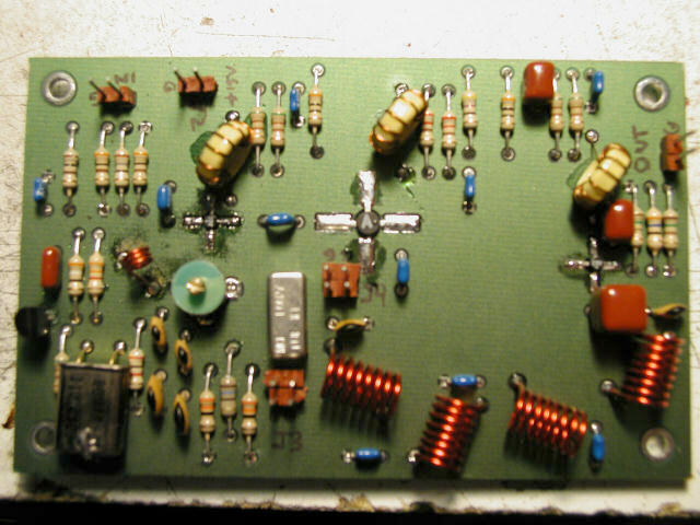
Here is another view of the Tracking Generator board. Once I got the second board working, it occurred to me that the first board would not be wasted, assuming I could get it working. The way the TG works is by taking the 110MHz - 180MHz (or tighter, depending on center frequency and span) swept VCO signal sampled through R109 (470 Ohms) on the First Local Oscillator and IF Mixer board and mixing it with 110MHz from the LO on the Tracking Generator board using a TUF-1. All the Tracking Generator is, is a buffered VHF LO and mixer with RF and IF amps--in other words, it's a Direct Conversion Receiver (or single stage of a superheterodyne)!
As far as I can tell, there is absolutely no reason why any signal in the 110MHz to 180MHz range could not be downconverted to a signal in the 0MHz to 70MHz range, using the Tracking Generator circuit/board unchanged. Most importantly, a signal in the range of 144MHz to 148MHz--the amateur radio 2-meter band--could be down converted to a signal in the range of 34MHz - 38MHz.
There is a downside. You won't be able to see even the first harmonic (144 x 2 = 288 - 110 = 178), but you will be able to see any spurs from the fundamental. Tap the VCO sample after being amplified by U1 and U2 (say via a switch at jumper W2), feed this signal into a 2-meter filter (or a return loss bridge), feed the output of the filter into this new downconverter and then feed the output of it into the 0MHz to 70MHz input on the Spectrum Analyzer, and you can perform the same tests as shown in Figure 3 of the November, 1999, QST Tracking Generator article! Now that's a useful piece of test equipment!