RF Chain Details
|
|
|
|
|
|
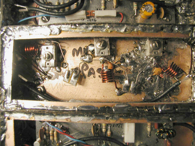
Ok, this is the 100MHz Bandpass Filter. It's an incredible design. Included with the kit is a QEX article talking about this particular triple-tuned filter. It does work quite well, and I see myself scaling it for other projects.
This was the site of the biggest screw up I made in this project. The kit comes with three very nice glass piston trimmer capacitors, and a couple of photos showing how to lay out the filter ("do it like in the photo and it will work"). Only problem was, I didn't have the same physical layout as in the photo. I had a box 1" x 2" x 5" to work with. Sam Billingsley, AE4GX, suggested using a false front to the enclosure to hold the piston trimmers (each about 1.5" long). This put the trimmers a little closer together than I would have liked, but did give me access to them from the front panel (in the previous section, you may have seen three holes in the front panel where you could access the trimmers with an Allen wrench). If you look closely at the compression trimmer on the far right, you'll see where this false front used to stretch from wall to wall in the compartment, about an inch from the front panel on the right.
Being really nervous about blowthrough in the filter, I decided to put little PC board baffles between the trimmers, perpendicular to the false front, sticking into the compartment, between the three trimmers.
Now, Wes, W7ZOI's cleverness in this filter, among other things, was to use "gimmick" capacitors to couple each stage of the filter. Wires go from each trimmer to a small piece of PCB material (see the notes on the filter with the kit). Well, I thought the gimmick capacitor was the PCB material, but actually, it's the stray capacitance (about 0.25-0.3pF) between the wires--totally defeated by my baffles I had installed between the trimmers. Getting no signal through the filter, I finally realized this, grabbed my needle nosed pliers and began to rip out the baffles.
What I did was destroyed one of the three glass trimmers. Ouch! And at 11PM on a Sunday, no less!
Fortunately, I had picked up some 1.5-20pF mica compression trimmers at a local surplus store. From a physical layout perspective, these were much better suited for my filter, anyway. So I set about removing the false front and baffles (taking care to not destroy the other two piston caps!) and rebuilding the filter. It worked, first time through. The one thing I can say about using the compression trimmers vs. the piston trimmers is that the piston trimmers have somewhat of a smoother, almost Vernier-like operation. The compression trimmers we MUCH sharper to tune. But I was able to get the filter tuned up pretty well, using my MFJ antenna analyzer as a 110MHz signal source and my 100MHz Tectronics scope (set on 10X frequency scale...first time I'd ever used that feature) to observe the filter peaks.
One very important thing to note about this filter. The purpose of this filter is to knock out the 90MHz image. But if you look closely at the QEX article, you'll notice that while you can peak the filter at the maximum pass-through for 110MHz, the actual sweet-spot is about 111-112MHz. Not a problem for the design purpose of this filter (although it drove me crazy at first).