RF Chain Details
|
|
|
|
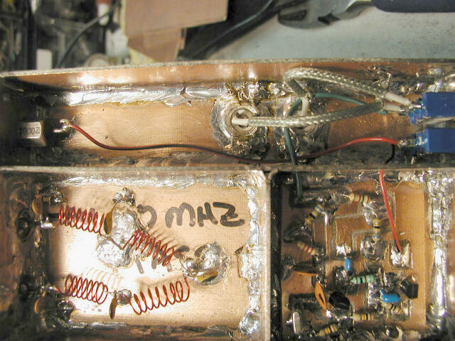
This photo shows the Crystal Calibrator In/Out Switch and Wiring (top), the 70 MHz Low Pass Filter (lower left) and the 10MHz Crystal Calibrator Oscillator (lower right). The "top" section and the calibrator oscillator section are not sealed. I decided that it was not necessary, because I also added a power switch to turn on/off the oscillator when needed. I've found that there are times when it's helpful to have the oscillator on, but the main input switched in. This has mixed results, but sometimes it's helpful to see the "ticks" every 10MHz along side the input signal. The green wire coming from the oscillator is the output. I routed it around the center conductor of the input line, to get some bleed over when the oscillator is turned on, as well. I think, were I to do it over, I'd skip the shielded wire here and get just a little more bleed over when the oscillator is on.
However, both boxes are sealed from the rest of the circuit and from outside (you don't want that megawatt FM station nearby getting in if you can avoid it...).
The input signal comes into the 20dB attenuator, in the section immediately "below" (actually, "above" when the SA is turned over in the normal operating position) the switch section--the two RCA plugs carry this input signal in and out of the attenuator compartment. The signal line goes directly from the input BNC to one of the RCA connectors, to the switch, back through the second RCA connector, to the attenuator In/Out switch to the pi pad.