RF Chain Details
|
|
|
|
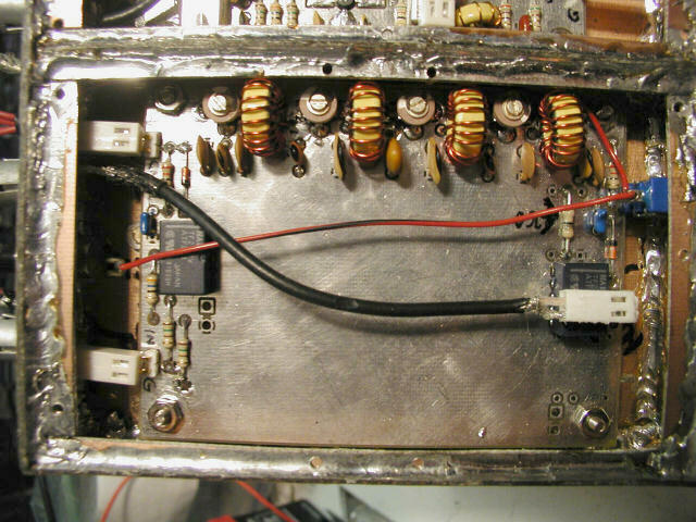
So far, I've only installed the basic 10MHz 300KHz-Resolution Bandpass Filter. This was probably the easiest board to build, although it took a little figuring out to make sure I had the relays in correctly. Also, I went ahead and installed a switch (on the front panel), but didn't label it until late in the project. It finally dawned on me, after two or three times of spending up to an hour trying to figure out what I had screwed up in the chain, that all I had done was set the narrow filter ON--even though there is no narrow filter--so no signal passed through the filter. Duh.
Quick pause for an interesting story. I tuned my filter up using a 10MHz signal generator, a 50 Ohm dummy load (it sure is nice to have 50 Ohm interstage connections!) and my oscilloscope. Then I took it over and put it up on Sam, AE4GX's W7ZOI/K7TAU Spectrum Analyzer. We hooked it up to his Tracking Generator (which he really hadn't used much), and noticed that the bandpass was actually a smidgen higher than the 10MHz tick in his calibrator. I knew it was tuned right, but decided I'd try again. Then it dawned on me--he was using the 110.7MHz crystal in his tracking generator, but hadn't tweeked his IF to 10.7MHz for the 30KHz crystal filter he had built but not installed. The TG was tracking 700KHz too high! So we tweeked his second LO (the trimmer will conveniently move the IF from 10 to 10.7) to 10.7MHz, and voila, my filter passband was EXACLTY were it should be!
But the greatest thing about this exercise is, no longer do I have to use the very shaky method of tuning the filter in the oscilloscope... I now have a Spectrum Analyzer!