IN3OTD's web site
...under perpetual construction.

The Skyworks SKY13374-397LF RF switch at HF
The SKY13374-397LF is a SPDT RF switch marketed primarily for the WCDMA band specified to work from 300 kHz to 6 GHz.
Its insertion loss and isolation were measured over the HF band and also tests with high power levels (up to 10 W) were done at 1.8 MHz, 10 MHz and 30 MHz.
The device uses a very small package (2 mm x 2 mm) with a pitch of 0.5 mm, which makes it a little difficult to use without a dedicated PCB.
The best solution would be to have a proper PCB fabricated by one of the many prototype manufacturers available on the Web nowadays, but since I was in a hurry I decided to try with the good old method of manually drawing and etching the PCB myself.
Usually I manually draw my test PCBs using a marker pen, which works often good enough. Since here the features size needed is quite small (the device pads should be 0.3 mm wide) it would be difficult to directly draw the traces using the marker pen, as the tip is too big to make such a fine line. So I first covered the entire PCB surface with the marker ink and then carefully (and patiently) scratched the ink away with the fine tip of a pair of tweezers.
The end result seems not too bad:
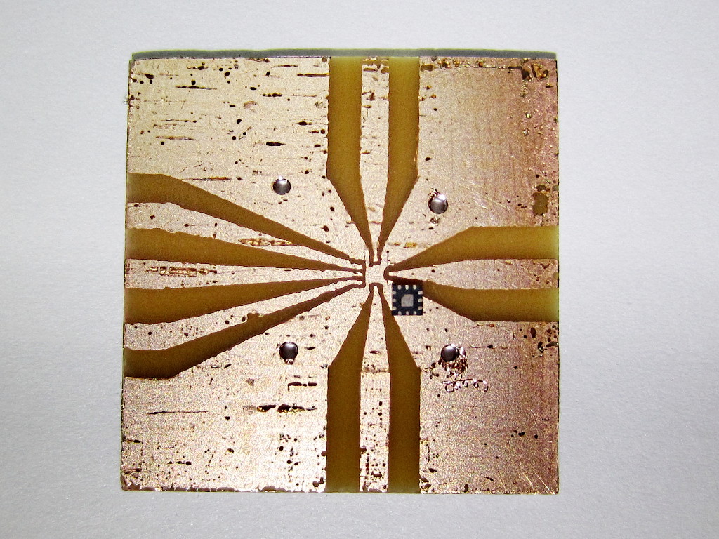
even if, as usual, some copper pitting and rough edges are present:
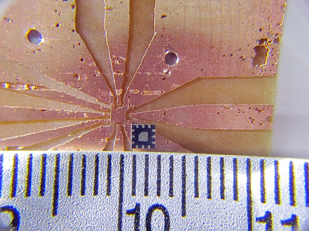
Soldering was not too easy: I used solder paste and at the first try I put too much in the center and the device remained suspended above a big blob of solder connected to the center pad.
After cleaning up the PCB and the device from the excess solder, I tried again, using less solder paste and a little helper to make sure that the device will contact the copper pads:
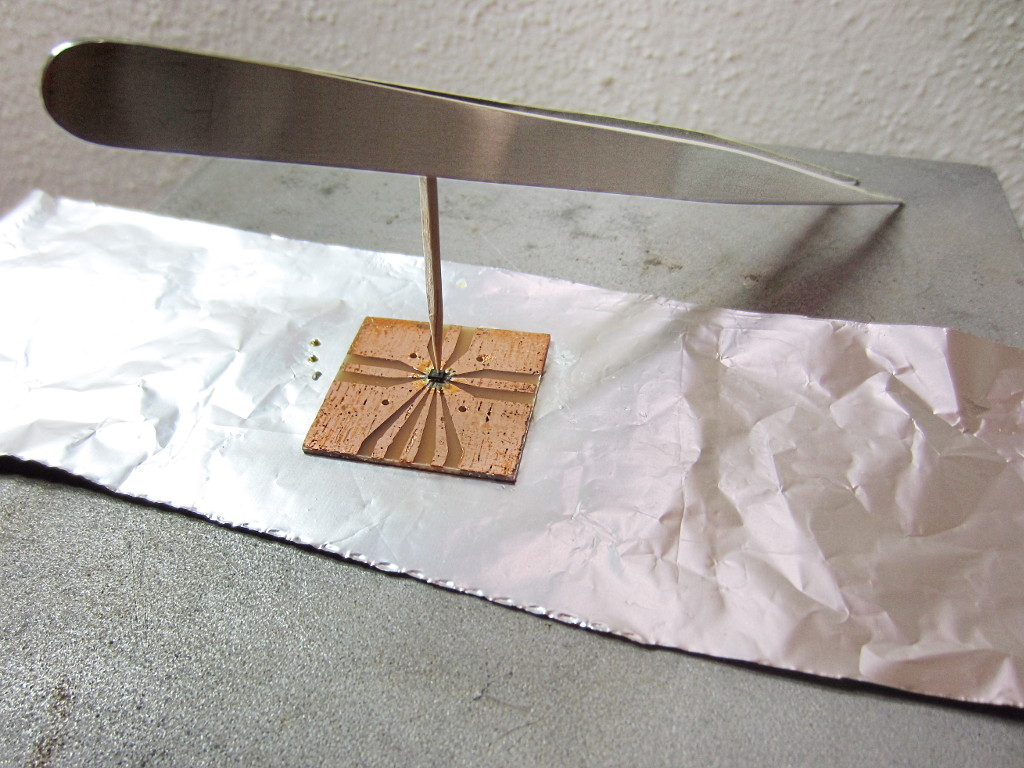
and, to my surprise, the soldering went well and all the pads were properly connected. Time to test the device performances:
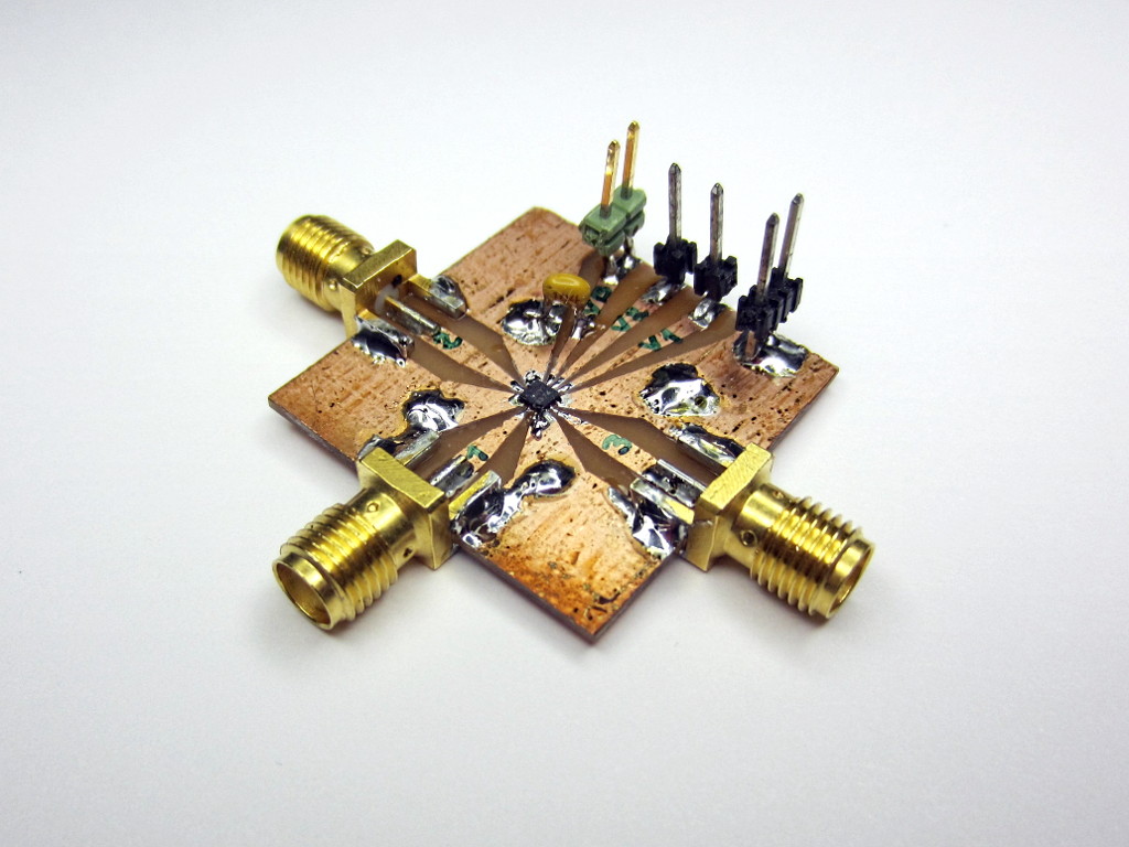
Small-signal S-parameters
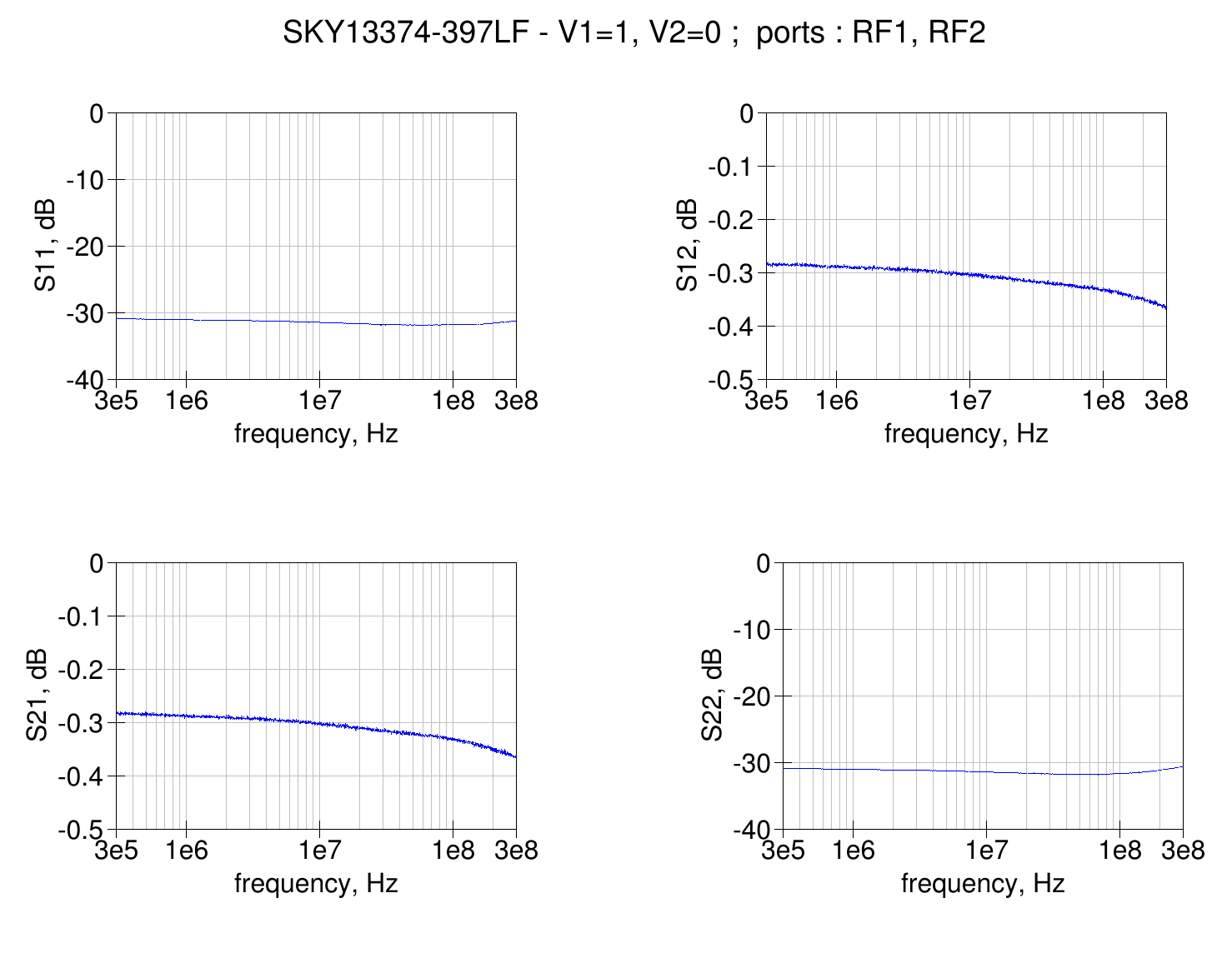
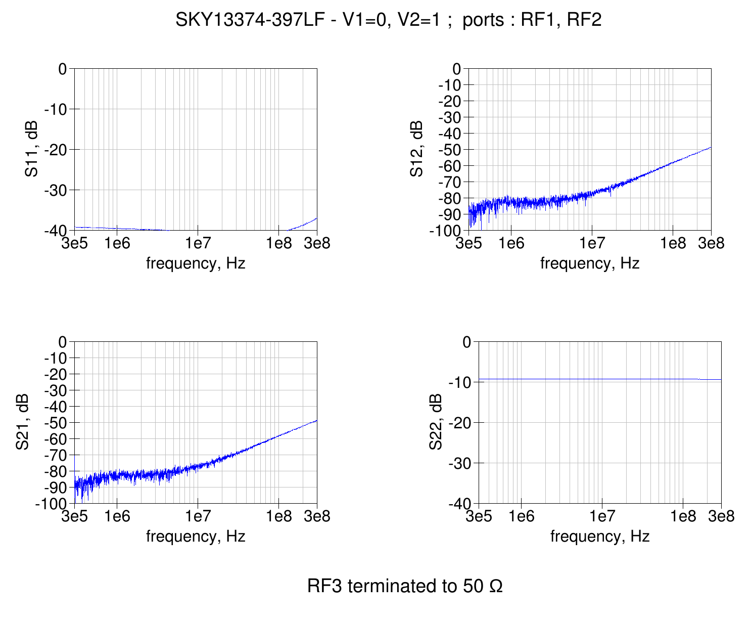
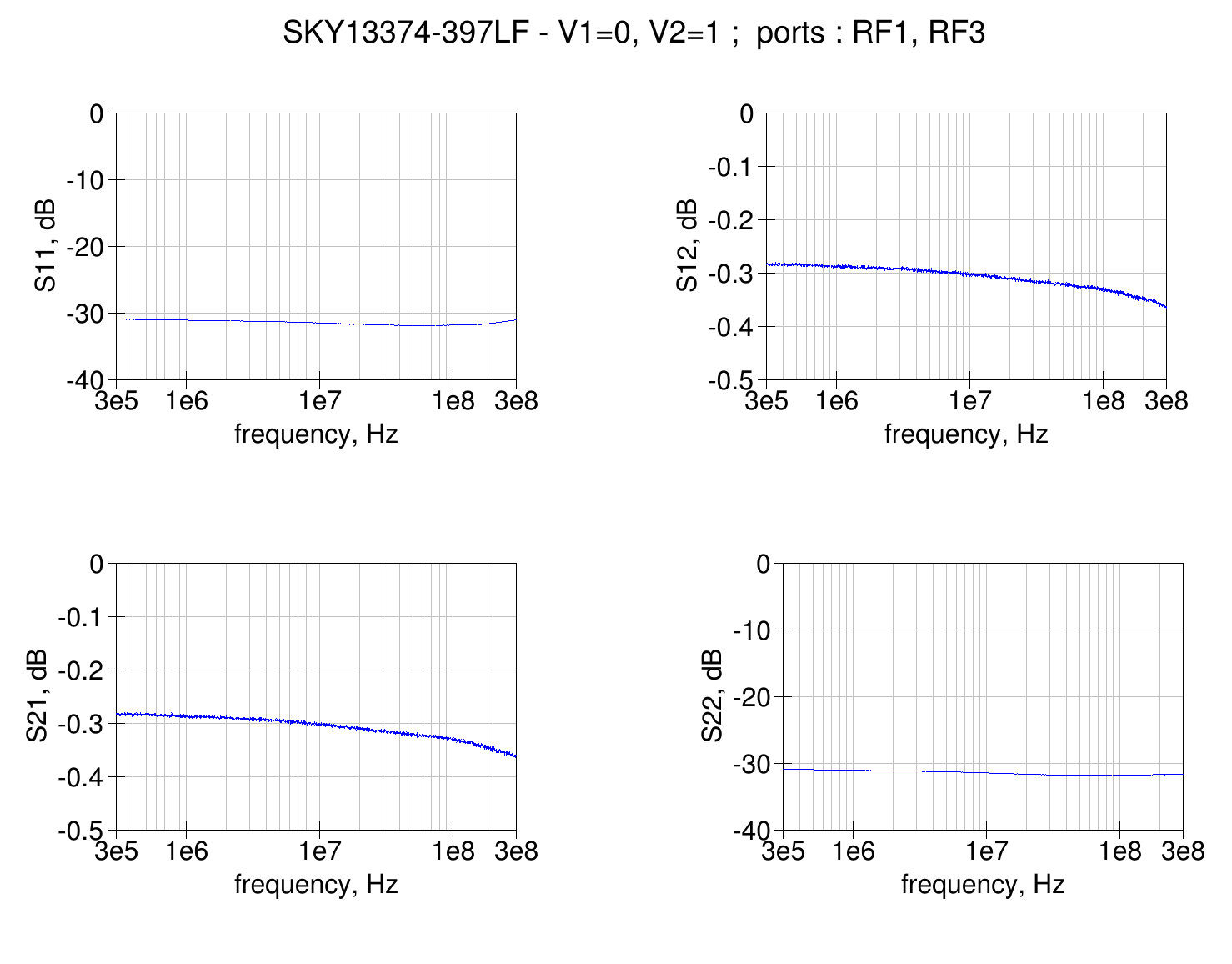
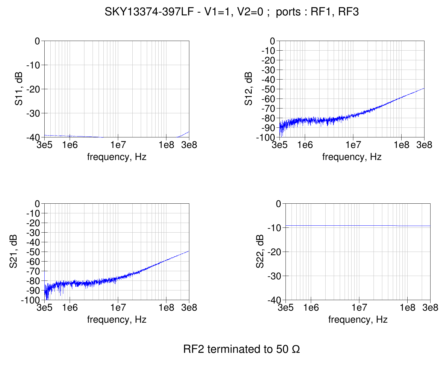
Here are the device S-parameters measured with a 0 dBm signal, for different switch configurations.
RF1 to RF2 path enabled
As expected, about 0.3 dB of losses and a good match on the ports.
RF1 to RF2 path disabled
The isolation when the path is not enabled is very good.
The common port (RF1) sees the termination which was connected to the RF3 port, so it shows a good match, while the isolated port (RF2) for some reason seems to have a 25 ohm termination resistance.<.p>
RF1 to RF3 path enabled
RF1 to RF3 path disabled
Harmonics level vs power
At 1.8 MHz
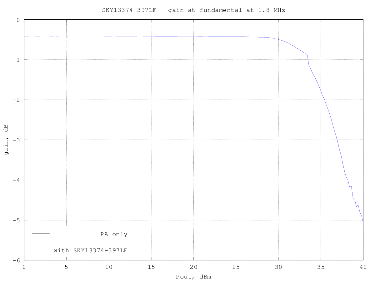
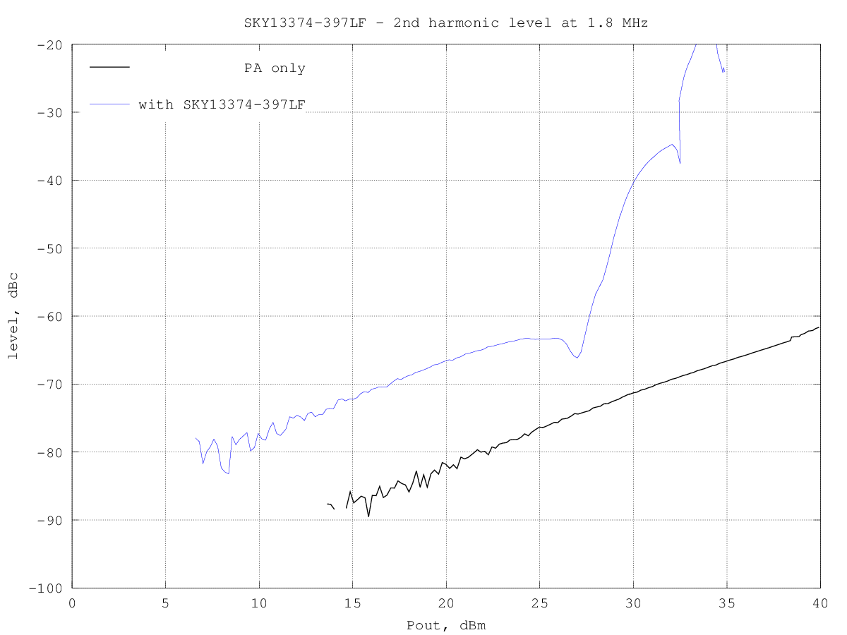
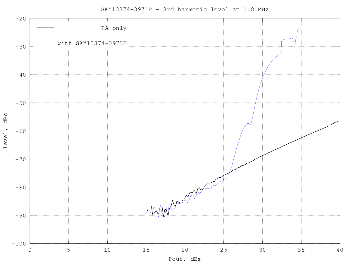
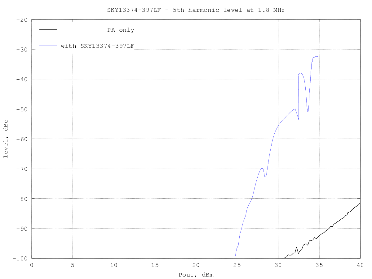
Unfortunately this switch seems to be good to about only 30 dBm at this frequency. The datasheet says it works up to 39 dBm, above 500 MHz.
SKY13374-397LF_H2_1.8MHz.png
SKY13374-397LF_H3_1.8MHz.png
SKY13374-397LF_H4_1.8MHz.png

SKY13374-397LF_H5_1.8MHz.png
At 10 MHz
The datasheet says it works up to 39 dBm, above 500 MHz.
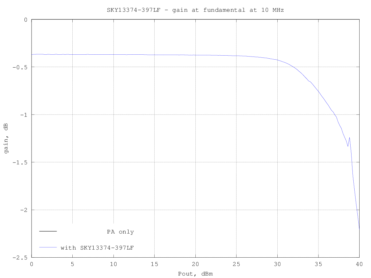
SKY13374-397LF_H2_10MHz.png
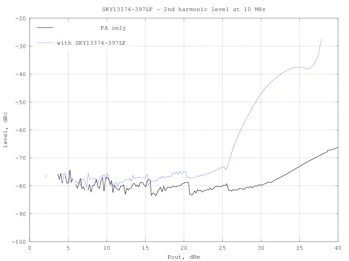
SKY13374-397LF_H3_10MHz.png
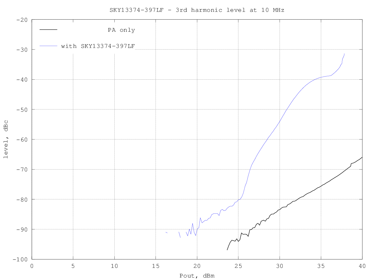
SKY13374-397LF_H4_10MHz.png
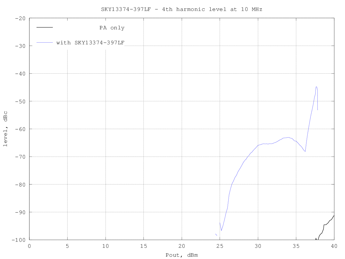
SKY13374-397LF_H5_10MHz.png
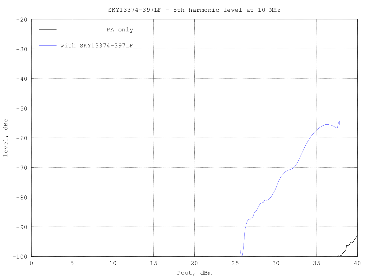
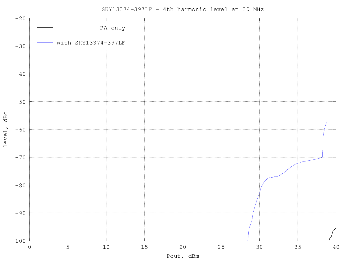
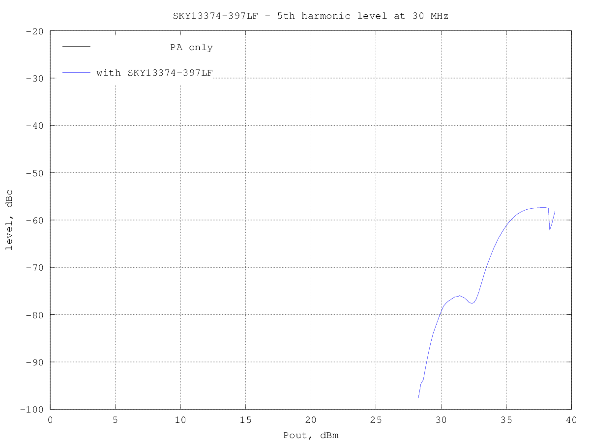
At 30 MHz
The datasheet says it works up to 39 dBm, above 500 MHz.
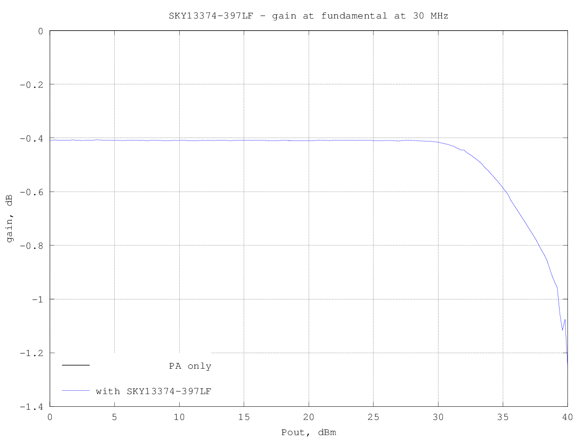
SKY13374-397LF_H2_30MHz.png
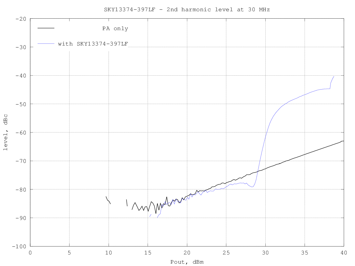
SKY13374-397LF_H3_30MHz.png
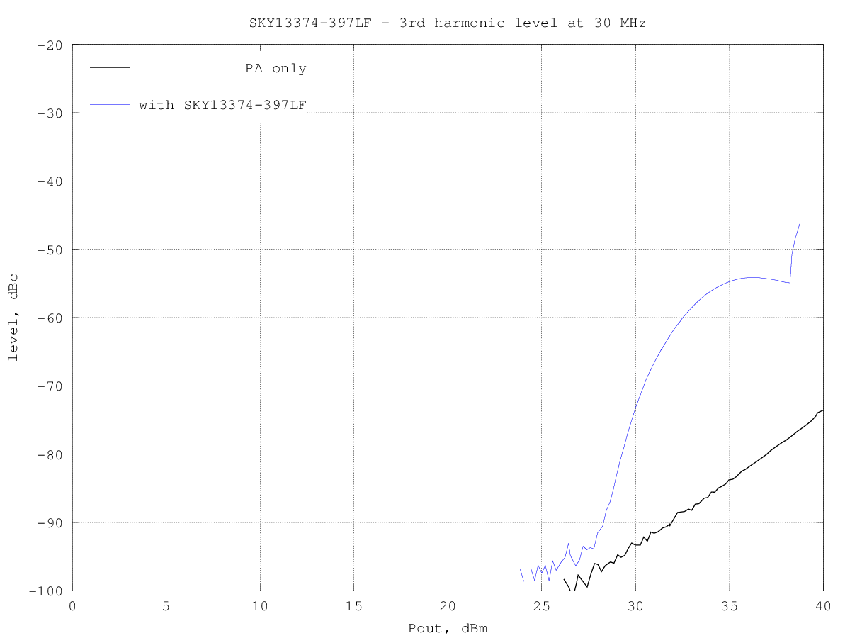
SKY13374-397LF_H4_30MHz.png
SKY13374-397LF_H5_30MHz.png
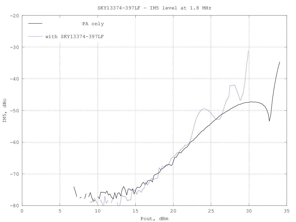
Intermodulation distortion vs power
At 1.8 MHz
SKY13374-397LF_IM3_1.8MHz.png
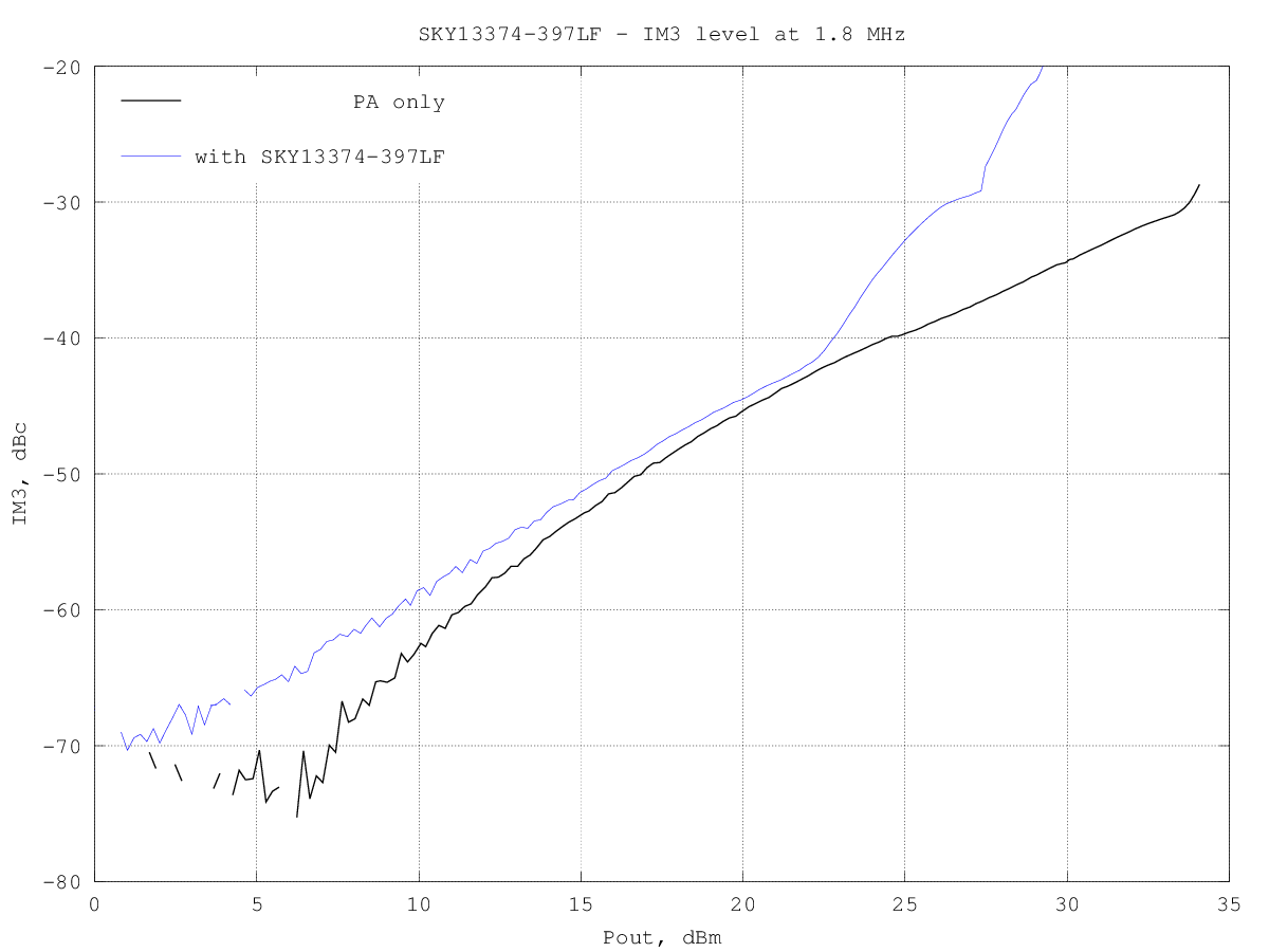
SKY13374-397LF_IM5_1.8MHz.png
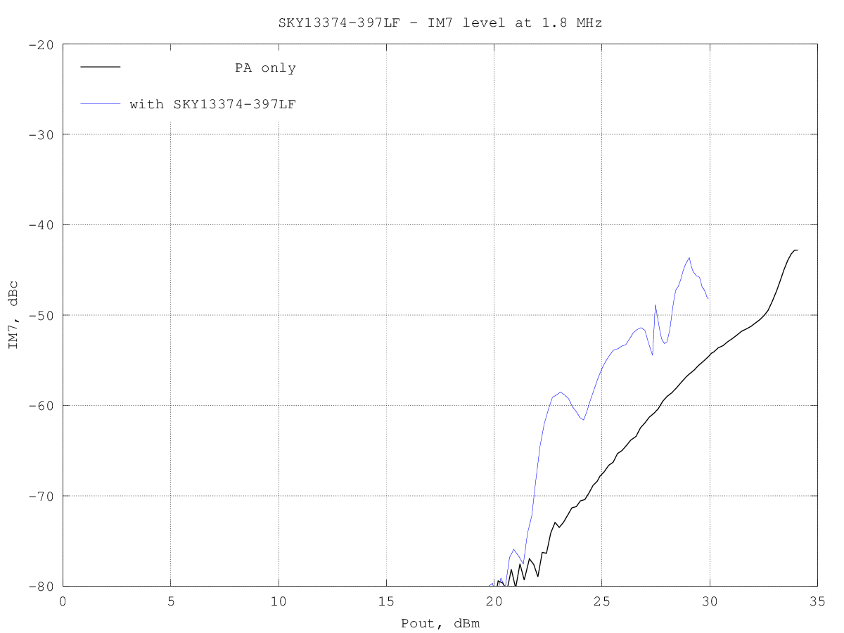
SKY13374-397LF_IM7_1.8MHz.png
At 10 MHz
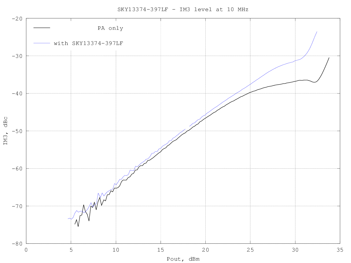
SKY13374-397LF_IM3_10MHz.png
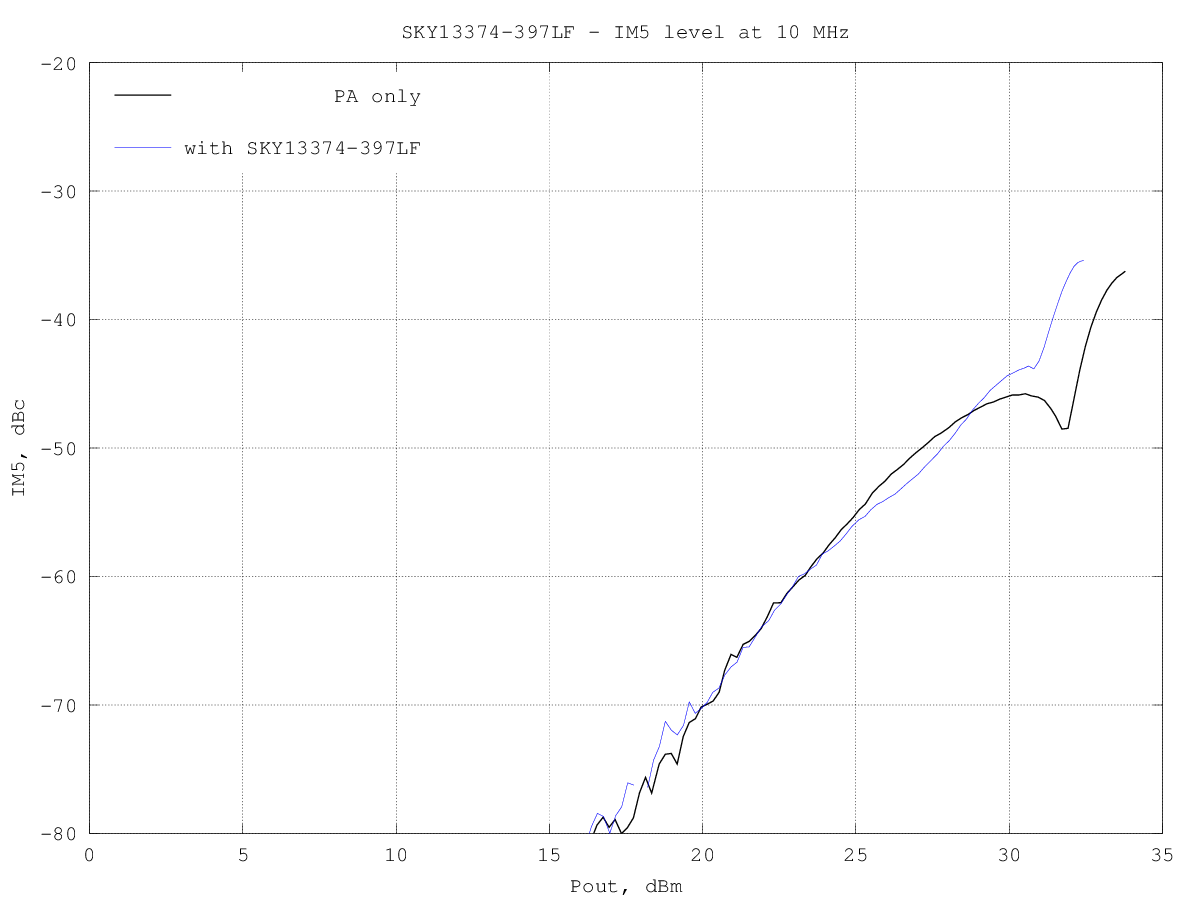
SKY13374-397LF_IM5_10MHz.png
SKY13374-397LF_IM7_10MHz.png

At 30 MHz
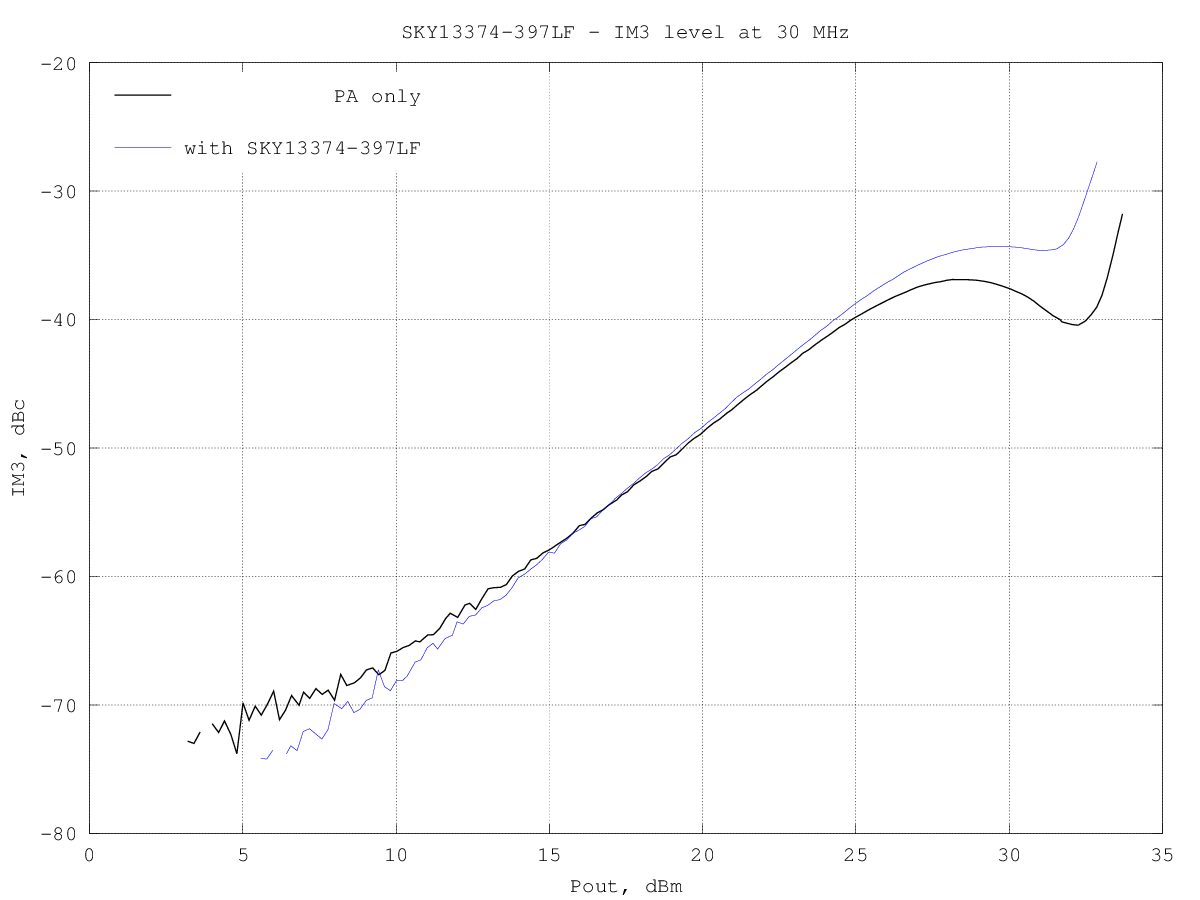
SKY13374-397LF_IM3_30MHz.png
SKY13374-397LF_IM5_30MHz.png
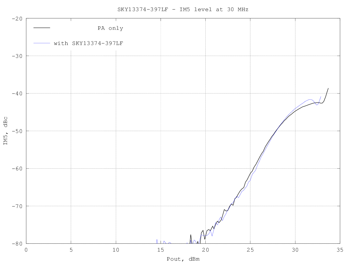
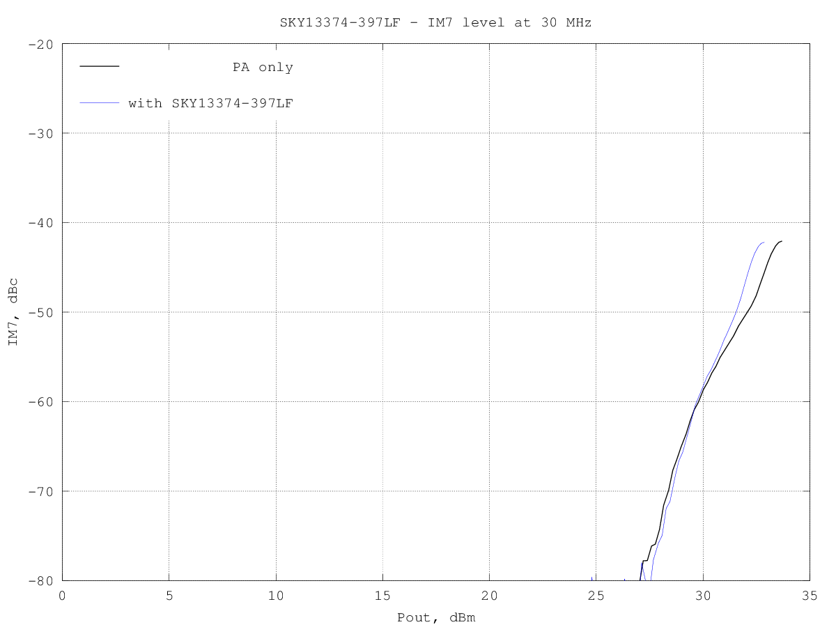
SKY13374-397LF_IM7_30MHz.png
Spurs in RX
The switch datasheet mentions an "internal negative voltage generator" which is likely used to generate the bias for the internal components; similar switches from other manufacturers have also internal bias generators, which are often sources of spurs and harmonics on the HF bands.
The switch was connected to the input of an Hermes-Lite SDR, with the input terminated with a 50 Ω load and the RX noise floor in a 500 Hz bandwidth measured throughout the HF band every 500 Hz.
The results is shown in the following graph:
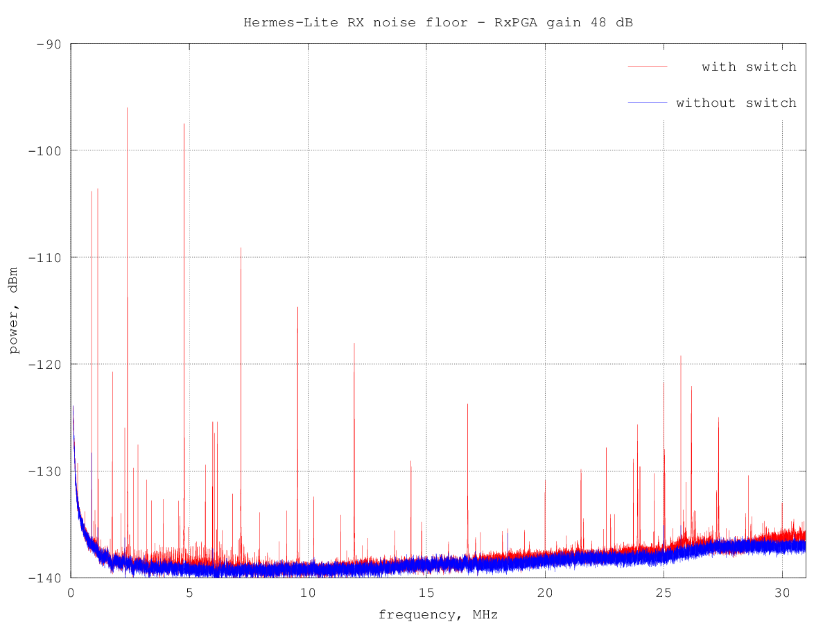
for comparison also the measured noise floor with just the 50 Ω at the input is shown.
There are several discrete lines, especially at the lower end of the HF; while some may be due to noise coupled from the power supply it's evident that this switch injects a significant noise on its ports.