|
Page last updated: 03/05/2013 |
Component tester
This component tester as an add on to a standard oscilloscope, used to check the characteristics of electronic components as an aid to fault finding. It is further possible to test components in circuit without there prior removal, or compare a faulty PCB to a know working unit. For fault finding within the electronics industry, this proves to be one of the more useful tool on the engineers toolbox perhaps only eclipsed by the humble multi-meter.
Design requirements
Basic oscilloscope, with two channel X-Y capability.
12Vac supply.
1k resistor, current limiting.
Suitable enclosure, connectors, cable etc.
Circuit description:
The schematic below shows the oscilloscope component tester add on in its most basic form
A simple to build, requiring no special test equipment and little or no test and setup procedures, the circuit is presented here is pretty much build and go. The most taxing issue being that of what enclosure to choose and where to fit the connectors.
But please don't be fooled, this little add on circuit will prove to be of far greater value than it's meagre component count, leaving one to wonder how I managed without such a tool for so long...
A slightly more sophisticated circuit is included below. There is however very little more in terms of functionality other than a power indicator, fuses for protection, connectors for power, and finally a battery bias supply to assist with testing components such as SCR's etc. The unit is built directly into its enclosure using point to point wiring technique hence there is no PCB.
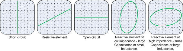
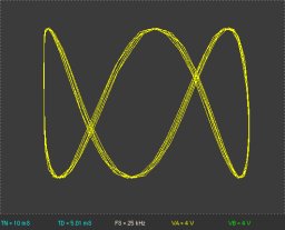
In operation 12vac is applied to the component or section of circuit to be tested, current limited by a 1k resistor. The oscilloscope X input measures the voltage applied to the component, whilst the Y input measures the voltage drop across the current limiting resistor and hence current passed by the component. Thus what is seen on the oscilloscope display is current (Y) against applied voltage (X) over the complete ac cycle, some of the results one might expect to see are shown below...
Expected results for passive components
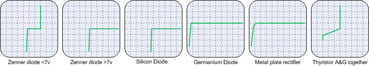
Expected results for semiconductor diodes
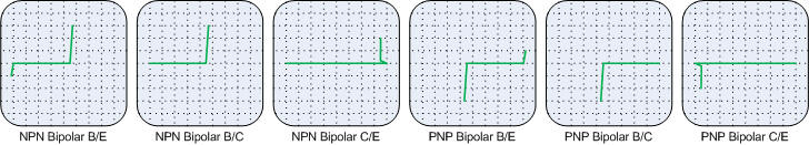
Expected results for semiconductor bipolar transistors
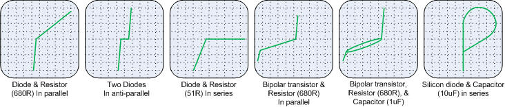
Expected results for mixed component types
 Components
tester parts listing:
Components
tester parts listing:
 Component tester expected trace patterns:
Original Files:
Further to the details of the pages above - the original CAD files created using EAGLE PCB Design software are included below, along with associated PDF files of both schematics and PCB layouts suitable for printing directly.
To use the original CAD files, they must be opened with EAGLE. Visit the CADsoft web site for more details, the software (including a freeware version), part libraries, tutorials, for EAGLE are available.
Component tester schematic PDF
Component tester Eagle schematic
Further reading & Reference material:
Dave Botto, Television June 1984.
Simple scope component tester adapter
Barry de Graaff B. Eng (Electronic Engineering) May 2002