LEARNING OBJECTIVES -
This section will be tested in a practical session separate from the written examination.
Construction - Recognise components
10a.1 Identify resistors, capacitors including fixed, variable and
electrolytic types, inductors, transformers, diodes, transistors,
integrated circuits, crystals, microphones and loudspeakers. Before you start a building project you need to be able to recognise the different components used in circuits. the images opposite and below show you examples of components that you need to be able to recognise.
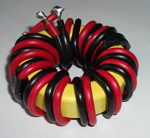
Toroidal transformer as used in a balun
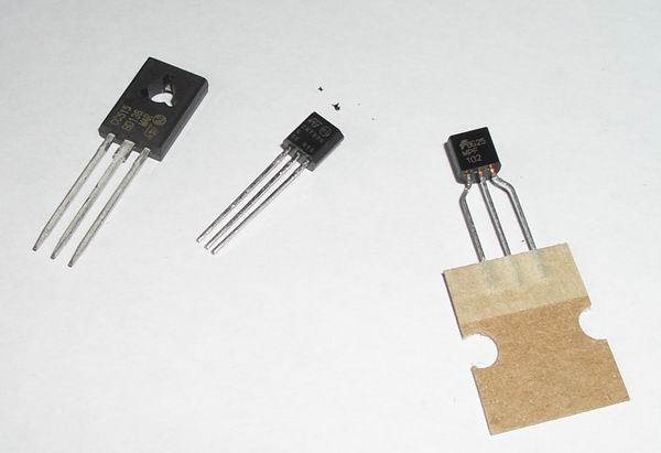
Transistors
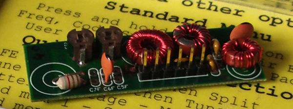
Diodes - Labelled D1 to 9 on the bottom of the drawing, these are used to switch different bandpass filters into line.
Integrated circuitsand Crystals. The integrated circuits are the many-pinned black structures. The crystal is the silver block in the centre.
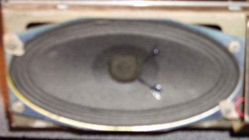
Loudspeaker
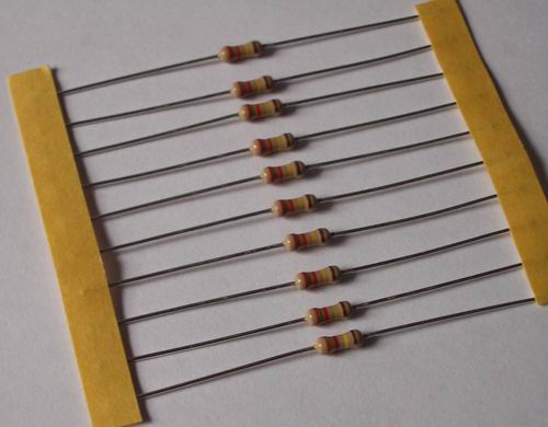
Resistors - provided in strips of the sane value.
Capacitors-
The top of this image shows some surface mount capacitors. On the
bottom left is a miniature trimmer (variable) capacitor.
Variable capacitor-part of a variable bandpass filter used in a home made receiver.
Inductors- The structures with red wire are toroidal inductors forming part of a bandpass circuit for a QRP transceiver.
Variable inductor- Used in an ATU
Microphones
Construction - Soldering basics
10b.1 Understand that soldering is a method of joining metal wires and components using a hot soldering iron to melt the solder. Most electronic components are
connected together on a circuit board using solder. This is a metal
that has a fairly low melting point. It looks like a thin wire and
comes in rolls. It is melted using a soldering iron.
10b.2 Recall that many solders contain a flux to help the solder to
flow and to prevent a layer of oxide forming on the surfaces to be
joined. Many solders contain a chemical
called a flux. This helps to lower the melting point of the solder so that
is flows onto the joint. Flux also prevents a layer of oxide forming on
the surfaces to be joined. The oxide is a bad conductor of electricity
and if formed would prevent electrons flowing and could cause a circuit to malfunction.
10b.3 Recall that some metals are easy to solder and some are difficult. Not all metals are easy to solder. The easiest are copper, silver and gold. Next come Iron, mild steel and nickel.Stainless steel and iron are the hardest. Aluminium is difficult to solder because it is covered in a layer of aluminium oxide.
10b.4 Understand that the tip of the soldering iron has to be cleaned
to help remove any oxide and then ‘tinned’ to prevent the oxide
re-forming and to improve the conduction of heat to the joint.
Recall the reason for tinning wires prior to soldering.
As a
soldering iron is used, the tip becomes black as oxide builds up. To
prevent this solder stations have a wet sponge attached. The oxide can
be wiped off on the sponge. The tip then touched onto solder to "tin"
it. This prevents the oxide building up. The wires attached to components are
also tinned. This makes it easier to solder them into place as the heat
is transferred more rapidly.
10b.5 Recall that it is necessary to make joints reasonably quickly to
avoid damage to components, and that most construction faults stem from
poor (dry) joints. The soldering iron needs to be hot
enough to melt the solder quickly. Heat should be applied to the joint
and then the solder. If the iron is at too low a temperature the component could be damaged by the heat transferred to
it. Components can also be damaged by applying a hot iron for too
long.This is particularly true for semiconductors. A
dry joint looks dull rather than
shiny and has a granular appearance. They are caused by insufficient
heat from the soldering iron, insufficient flux and by moving the
component before the joint has "set" properly. The result is a
joint that does not conduct, can cause noise and intermittent
connections.
See this web site to show the stages in soldering a joint
Colour code 10c.1 Recall
the resistor colour code, colours 0 to 9 with gold as multiplier.
Recall silver (10%) and gold (5%) as tolerance bands. Identify the
value of a resistor between 1Ω and 9MΩ from the E12 series.
Traditional resistors use a colour code to indicate their value and tolerance
The tolerance band is gold for 5% and silver for 10%. This means that a
1k Ohm resistor with a silver band could be anywhere in value between
900 and 1100 Ohms
The three bands at the end give the value of the resistor.
Band 1 gives the first digit
Band 2 gives the second digit
band 3 gives the multiplier
So, the resistor in the diagram is
Band 1 = Blue = 4
Band 2= Red = 2
Band 3= Red = 2 (means the number of zeros to add)
Total resistance = 4200 Ohms or 4.2 kOhms
.
Colours
Black = 0 Brown= 1 Red = 2 Orange =3 Yellow = 4 Green = 5 Blue = 6 Violet = 7 Grey = 8 White =9 Note that Red to Violet are nearly the colours of the rainbow (minus indigo)