| ADVANCED LESSON 58 |  |
| LEARNING OBJECTIVES and NOTES | |
| EMC - Filters 1 | |
|
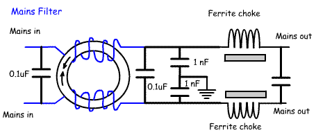
7b.1 Understand the construction and use of a typical mains filter. Interference is frequently carried from one piece of electrical equipment to another along the mains. To prevent this interference entering equipment a mains filter can be fitted. There are many designs available. One of the simplest consists of winding the cable suspected of carrying unwanted RF around a ferrite toroid. For example: Wind part of the mains cable used by a computer modem on a ferrite toroid to reduce the entry of RF into the modem. A more advanced mains filter is shown in the diagram opposite. This consists of a ferrite ring with 2 wires wound round in opposite directions to form a common mode choke. The capacitors allow any RF interference to pass to earth. the ferrite chokes remove non-common-mode interference. |
 |
|
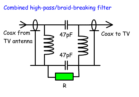
7b.2 Identify a typical circuit of a braid-breaking filter and a combined high-pass/braid-breaking filter. Understand their use. Understand why a ferrite ring will attenuate common-mode currents without affecting the differential-mode wanted signal. To reduce the level of RF travelling on the outside of coax braid (yes, you can have two separate signals on the coax braid, one travels down the inside and the other down the outside). The common mode current is on the outside of the braid and is not balanced. The current flowing down the inside of the braid is balanced by the current flowing down the central wire of the coax cable part of the coax can be wound around a ferrite toroid. This is just the same as the method described above to reduce RF in mains cables. A common filter used to remove the RF picked up by UHF TV coax consists of a combined high pass filter and braid breaking filter. This is shown in the drawing opposite. The inductors and capacitors form a high pass filter allowing TV signals above 470MHz to pass through whilst at the same time attenuating RF pick-up from amateur interference below 470MHz. The 47pF coupling capacitors have a high impedance at lower frequencies, and therefore block the unwanted RF currents. The break in the braid removes common-mode current. R is about 10k ohms and allows static discharge across the braid without upsetting the braid breaking characteristic of this filter. Understanding why a ferrite ring will attenuate common-mode currents without affecting the differential-mode wanted signal is easiest to understand when talking about pick up of RF by audio leads. Winding the audio lead around a ferrite toroid increases resistance to RF signals. In the case of an audio lead, this is the Common-mode RF. The resistance to audio frequencies is much lower and so the differential-mode currents are nor attenuated. |
 |