| ADVANCED LESSON 52 |  |
| LEARNING OBJECTIVES and NOTES | |
| Antenna Matching Units | |
|
5e.1 Understand that AMUs (ATUs) can “tune-out” reactive components of
the antenna system feed-point impedance (before or after the feeder)
and can transform impedances to an acceptable resistive value. Often called an Antenna Tuning Unit (ATU) this box of wide spaced large variable capacitors, large inductors and switches is used to match the antenna feeder to the input/output of a transceiver. It carries out several functions:
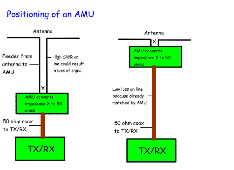
It is placed between the antenna and SWR meter and the transceiver. Ideally it should be placed at the antenna end of the feeder, but this is only possible if it is either a single band AMU or an auto ATU controlled by relays over a control line. In practice ATUs tend to be placed in the shack next to the transceiver so the operator can easily adjust it without going outside! |
 |
|
Understand that if the AMU is located at the transmitter, it will have
no effect on the actual SWR on the feeder between the AMU and antenna. If the AMU is placed next to the transmitter, then it does not alter the impedance of the transmission line from the antenna. It "sees" an impedance at the end of the feedline and is adjusted to match this impedance to that of the transceiver. |
|
|
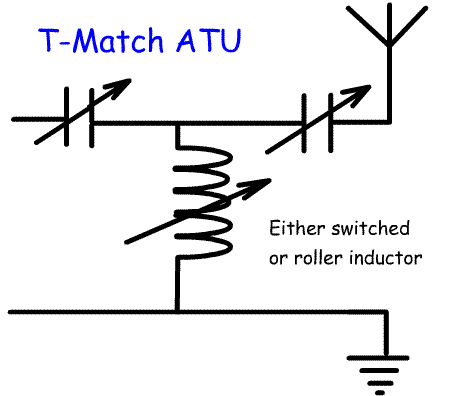
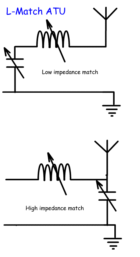
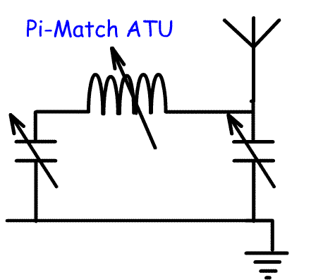
Identify typical AMU circuits (i.e. T, Pi and L circuits). There are different ways of arranging the inductors and capacitors to make an AMU. The three main types are named after their shapes:
|
   |