| ADVANCED LESSON 47 |  |
| LEARNING OBJECTIVES and NOTES | |
| Down-converters and transverters | |
|
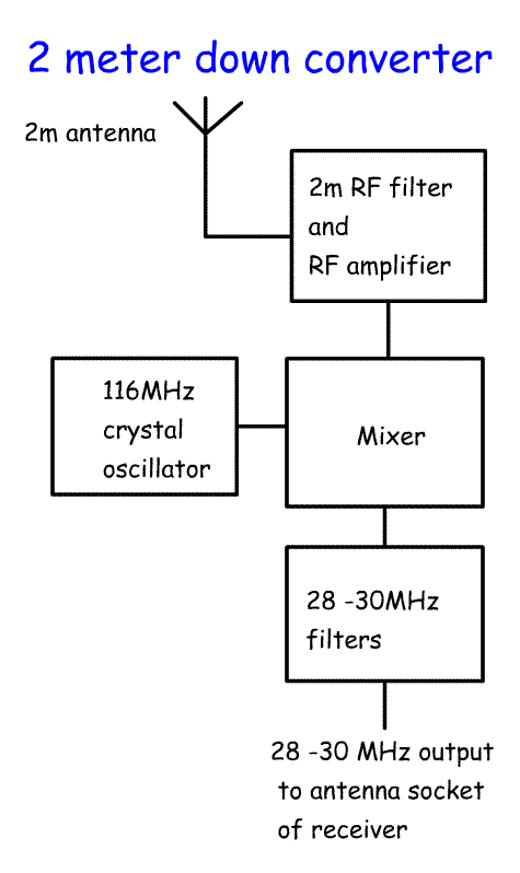
4q.1 Understand that VHF and UHF operation can be carried out by using down converters and transverters ahead of HF equipment. Some older rigs do not have 6m, 4m, 2m and 70cm. One way to get onto these bands is to build a down converter for reception or a transverter for transmission and reception. A common IF is the 28 - 30MHz band as this is 2MHz wide. For a receiver only the down converter requires a 2m filter attached to a 2m antenna. The RF amplifier boosts the 2m signal and feeds it into the mixer along with 116MHz input from a crystal oscillator or a fundamental crystal multiplied up to 116MHz. One of the outputs will be 144-116 = 28MHz to 146-116 = 30MHz The 28 to 30 MHz filters remove other mixer products. The 28MHz - 30MHz is fed into the antenna socket of the HF transceiver which carries out all the functions required to produce an audio signal. |
 |
| In a transverter the receiver works as above. On transmit the PTT applies power to the antenna change-over relay and to the transmit parts of the circuit. A low power signal is fed into the 28-30MHz input. In some HF transceivers there is a separate low power output. If this does not exist turn the power on the transceiver as low as possible. If this is still not low enough insert an attenuator before the 28-30MHz filters to reduce the power. This will need to be constructed to dissipate the heat produced and to have a 50 ohm input and output. Attenuators consist of 3 transistors arranged in a Pi configuration. The 28 to 30 MHz output from the main HF rig is mixed with the 116MHz oscillator to produce an output from 144 to 146 MHz. This then filtered and passed to a 2M PA stage which applies RF to the antenna. |
 |
|
Transceivers |
|
| 4r.1 Understand that transceivers normally share oscillators between
the transmitter and receiver circuits; and they may use common i.f.
filters to limit both the transmitter and receiver bandwidths and that
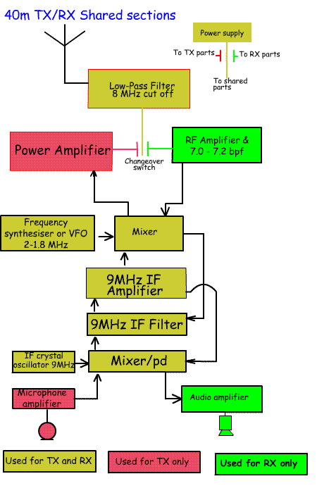
they also use common change-over circuits. Some parts of transceivers are shared between transmit and receive: These include:
|

|
|
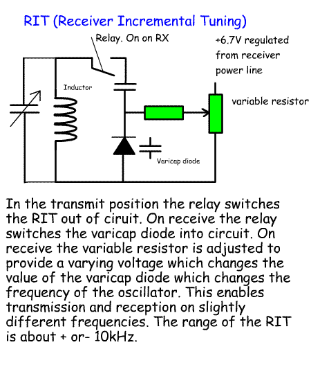
Recall the function and use of the RIT control. The RIT control stands for receiver incremental tune. This could be a varicap diode across the VFO. If a received station is not quite on your frequency, switch on the RIT and adjust the VFO frequency to him them in. On transmit, the RIT is switched off so as not to alter the transmit frequency. |

|