| ADVANCED LESSON 44 |  |
| LEARNING OBJECTIVES and NOTES | |
| Mixer and Local Oscillators and IF Amplifiers | |
|
4m.1 Understand the function of a mixer, the generation of the intermediate frequency (IF) and other mixer products. Understand that for given RF and IF frequencies, there is a choice of two possible local oscillator (LO) frequencies. Understand the reasons for the choice and calculate the frequencies. The mixer is used to convert an incoming signal to an IF frequency. A mixer will take the two inputs and produce a number of outputs. For example a 3.6MHz signal when mixed with a VFO running at 5.4 MHz will produce a number of outputs: 3.6 + 5.4 = 9MHz 5.4-3.6 = 1.8MHz 3.6MHz 5.4MHz (3,6x2) +5.4 = 12.6MHz (3.6x2) -5.4 = 1.8MHz and many others! Lets assume we have a crystal filter of 9MHz, then we would use this to select the 3.6+5.4 combination. We could also have used a 1.8MHz filter to select 5.4-3.6 But notice that the second harmonic of 3.6 is 7.2 which would mix with -5.4 to also produce 1.8MHz. In general if you are building a basic VFO then choose a low frequency as these are more stable. If you are using a synthesiser then as these are more stable you could use the synthesiser in place of the 5.4MHz VFO. It as always worth looking at the mixer products to see if there are any unforeseen outputs from the mixer which could cause problems. |
|
|
4m.2 Understand the origin of the second channel or image frequency and calculate the frequency from given parameters. Second channel interference occurs when the wrong signal mixes with the output from the VFO. For example in a 145MHz receiver and a 10.7MHz IF the local oscillator could be run at 155.7MHz or 134.3MHz 155.7-145.0 = 10.7 145.0 - 134.3= 10.7 Assume we have chosen a 134.3 local oscillator If there is a strong signal from a nearby aircraft ground station on 123.6 this could also mix to produce 134.3-123.6=10.7. To prevent this we could choose to use a 155.7 local oscillator. We could also have very good filters at the front which filter out the 123.6 MHz signal. The lower the IF the harder it is to design the front end filter. For example a 455kHz IF would receive an image frequency only 455x2 = 910kHz away. |
|
| IF amplifier | |
|
4n.1 Understand the advantages and disadvantages of high and low
intermediate frequencies and the rationale for the double
superhet. We have already looked at this, but it won't do any harm to repeat that high frequency IF stages are better at removing image frequencies. Low frequency IF stages have more gain and filters tend to be cheaper. |
|
|
4n.2 Understand the operation of an IF amplifier and the IF transformer. An IF amplifier is designed to
|
|
|
Understand the concept of two LC tuned circuits utilising transformer
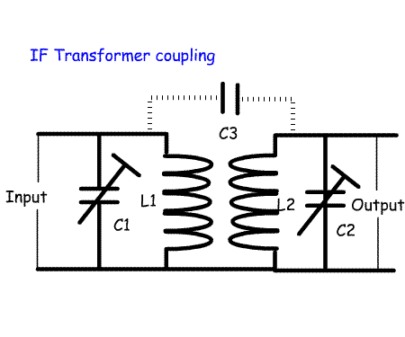
coupling. Identify critical and over-coupled response curves. The drawing shows opposite shows two LC tuned circuits from an IF stage. By tuning them to the IF frequency they will remove unwanted frequencies from the IF chain. As an alternating current passes through the first coil (L1) it induces a current in the second (L2) in a similar way to a mains transformer. The two coils are tuned with capacitors (C1 and C2). To adjust the frequency either a ferrite slug can be adjusted in the coils, or a variable trimmer capacitor adjusted to bring the circuits to resonance. The degree of coupling between the two will alter the shape of the output. There are different ways of adjusting the coupling:
If the coils are undercoupled (e.g. the coils are too far apart the loss increases because the electromagnetic field at the input does not transfer all rf power to the secondary of the transformer. The correct coupling is called critical coupling where there is one peak and the loss is about 5 dB. This loss is easily made up by the gain of the IF transistors or ICs |
  |
|
Understand how the gain of an IF amplifier can be varied, how this may
cause distortion and how the effects of the distortion are avoided.
Note: the reason to vary the gain (AGC) is covered at item 4p. The gain of the IF stage can be varied to alter the loudness of signal coming from the speaker. This can be done manually by having a potentiometer that alters the gain of the semiconductors in the IF stage. It can also be done using an AGC as explained in lesson 46. The time the AGC voltage is applied to the IF stage depends on the mode of reception. SSB is best received using a long delay so that the background noise does not rise between words. CW requires a fast AGC. If signals are very strong, too much gain can lead to overdriving the IF stage which leads to distortion |