| LEARNING OBJECTIVES and NOTE |
|
| Inductance |
|
Understand the term ‘self inductance’ and recall that a ‘back EMF.’ is
produced as current flow changes in an inductor.
Recall that the inductance of a coil increases with increasing number
of turns, increasing coil diameter and decreasing spacing between turns |
|
In this lesson we
are going to learn about what happens when an electric current is
passed through wire.
If an electric current passes through a straight wire a magnetic field
is created around the wire. This is called self inductance
and can be detected by placing a compass next to a wire. When the
current flows through the wire, a magnetic field is
created and the needle of the compass placed near the wire will move.
If the wire is wound into a coil connected to a battery and the switch
closed, the magnetic field increases and the
compass needle can be moved further away and still be seen to deflect.
Further increases in self inductance can be achieved by further
increasing the number of turns on the coil; increasing the diameter of
the coil; decreasing the spacing between the turns on the coil; placing
a high permeability core inside the coil.
The henry is the basic unit
used to measure inductance and has the symbol H.
Smaller units are often more convenient for radio work:
a millihenry (mH) is one thousandth of a henry. |
|
Understand the rise and fall of current in an LR circuit.
When a DC
power source is connected to an inductor via a resistor, the current
will start to increase as shown in the graph. The increasing current in
the inductor will cause an instantaneous negative voltage . This is
known as the back EMF. The two voltages will be equal, but
opposite in polarity and so no current will flow. The back
EMF will
start to rise eventually reaching zero. As the voltage rises, so will
the current. Eventually the voltage will reach a maximum and the
current will level off.
When the source voltage is removed from the coil by switching to
the opposite position, the current will flow through the resistor and
be reduced to zero over a period of time. The induced voltage will also
be reduced to zero.
In a DC circuit, the time taken
to
reach a steady current will be very short and only occur once as the
power is connected and once when the power is disconnected.
In an AC circuit this will be
happening continuously as the voltage moves from positive, to zero, to
negative and then back to positive. Changes will also depend on the frequency
of the applied voltage.
|
|
Understand
the use of high permeability cores and slug tuning.
In
modern miniaturised circuits it is important to reduce the size of
components. Inductors in the past have been quite large. Nowadays. they
are miniaturised by winding them on cores with a high permeability. This
means that only a few turns of very thin wire are required to produce a
small inductor but with a high inductance.
To allow the value of inductors
to be adjusted they are wound on formers with a small cylinder of a
material inside the former such as ferrite which has a permeability
higher than 1, for example ferrite.. The ferrite can be screwed in and
out of the coil thus
adjusting the inductance to tune a circuit. You have to be very careful
using metal screwdrivers
as the slugs are easily
broken . Us a special
tool designed for the job. The inductance can be lowered using a slug
with a permeability less than 1 such as brass.
|
|
Understand and apply the formulae for calculating the combined values
of inductors in series and
in parallel
In
the same way that capacitors and resistors can be connected in series
or parallel to create a new value, inductors can also be connected in
series and parallel.
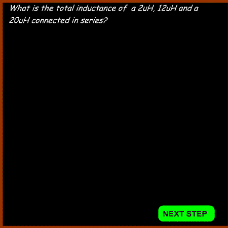
The formula to calculate the total value of three inductors in series is:

|
Inductors in series
Example 1

|
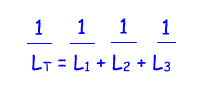
The formula to calculate the total value of three inductors in parallel is:

|
Inductors in parallel
Example 2

|

