| ADVANCED LESSON 17 |  |
| LEARNING OBJECTIVES and NOTES | ||
| Capacitance 1. | ||
| Introduction Capacitors allow AC to pass through, but block DC. They can be used to "drain away" any AC in a DC circuit - decoupling capacitors. They hold a charge and can be used in a variety of circuits e.g. timing circuits, Smoothing DC output of a power supply after the rectification stage.. They come in a variety of types for use in different circuits. |
||
| Understand the factors influencing the capacitance of a capacitor; area
and separation of the plates, permittivity of dielectrics and formula
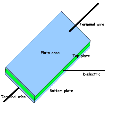
C=KA/d. A capacitor is made up of two or more flat parallel metal plates separated by a space filled with an electrical insulating material called a dielectric. This could be air, a vacuum, plastic, ceramic, oxide, plastic. • One lead is connected to one plate and one to the other. CAPACITANCE AND CHARGE •The Unit of Capacitance is the FARAD.
•A capacitance of 1 FARAD is when 1 Coulomb of charge is stored with 1 Volt PD. There are 6.241506×10¹⁸ electrons in a coulomb, but don’t bother learning this!.
[Q - charge in coulombs (C); C – capacitance in farads (F); V - potential difference in volts (V)] •Q=CV or
•One Farad is rather large so uF, nF, pF are more commonly used.Q / C = V or Q / V = C |
 |
|
The formula for calculating the capacitance of a parallel plate capacitor is: where k= εoεr where k= εoεrWhere, k=dialectric constant of the material between the plates (εr) x 8.854x10⁻¹² (εo) Where C=capacitance in Farads, k=dialectric constant ( between plates) A is the area of the plates in metres and d is the distance between plates in metres. The factors influencing the capacitance of a capacitor For the exam the key things to remember are.
|
 Example 1  |
|
Features of electrolytic capacitors:
|

|
|
Recall that different dielectrics are used for different purposes, e.g.
air, ceramic, mica and polyester; and that with some dielectrics,
losses increase with increasing frequency.
Some dialectrics show an increasing loss with increasing frequency. |
Dialectrics Some common dialectrics constances: Vacuum= 1 Ceramic in NPO capacitor= 15-100 Mica = 4-9 Polyester resin =2.8-4.5 |
|
| Breakdown voltage Understand that capacitors have a breakdown voltage and that they need to be used within that voltage. Capacitors are rated at a certain voltage. Above this voltage the dielectric will allow current to flow. In an air spaced capacitor you will see a blue light/arc as the electrons flow through the air. In a capacitor with a solid dielectric it will probably melt. The capacitor is then useless. |