Solid State Circuits 4 -
1. Wien Bridge Notch Filter
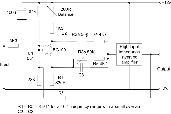
This is a useful filter for a simple distortion meter for use with communications equipment where distortion levels of 1 -
As shown the tuning mechanism uses a dual gang variable resistor but the capacitors could be made variable instead. The latter will require very high value resistors at R3 and R4 to tune down to 300Hz or less.
The tuning and balance points are extremely sharp so a small dual gang variable resistor, say 2K5, may be wired in series with R3a/b to act as a fine tune control with a suitable adjustment in the values of R4 and R5 to obtain the desired frequency coverage.
As shown the tuning range will be 10:1. However, if a lesser range is required, say 3.2:1 then R4 and R5 may be increased in value -
Depending on the signal levels involved, operation on a supply of greater than 12V will provide lower distortion in the phase splitter. Good screening of all circuits will be required and the supply should be well regulated and hum free.
C2 = C3 = 1800pF will provide a tuning range of approximately 1.55-
This is the basic circuit with additional gain and negative feedback provided in order to ensure that the width of any part of the notch does not significantly affect the individual harmonics of the signal being measured. The minimum LF response will be determined by the value C1 and the notch tuning by the values of C2 and C3. R32 should have a tracking accuracy of 2% or better -
Using Amplifier 6 from this page for the inverting amplifier and setting Rf to 22K gives an overall gain of x5.4.
To complete a basic distortion meter the linear detector from this page and a calibrated stepped attenuator are required.
More details to follow.