Scope Probe Information
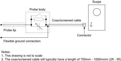
2. A Simple Scope Probe. The drawing to the right shows the outline and circuit of a simple switchable 10:1 / 1:1 scope probe.
With the switch open the probe has a 10x attenuation and the impedance at the tip will be 10Meg in parallel with about 7.5pF, with the switch closed there is no attenuation and the impedance at the tip will be 1Meg in parallel with about 60pF. The exact capacitance will depend on the scope and coax cable used.
The coax connector should match whatever is already present on the Y input of the scope -
Assuming that the scope input resistance is 1Meg then the probe resistor should be 9Meg. The probe compensation trimmer capacitor will be one ninth of the sum of the screened cable capacitance and the input capacitance of the scope and typically in the range 5pF -
The probe body should be screened and connected to the coax cable braiding to minimise proximity effects from your hand and external signal pickup.
Probes with other attenuation factors are available -
1. General. Oscilloscope (scope) probes provide a useful way to look at signals in various types of circuit as long as the user understands their few side effects. The probes are light weight with an insulated case and a very flexible screened lead. Switchable types offer 1:1 or 10:1 attenuation positions with the latter providing a significantly lower level of capacitance to reduce the loading on the circuit being measured. Some modern scopes have a preamp to offset the attenuation of the probe.
Commercial scope probes use a special light weight screened cable with a very thin inner, slightly resistive conductor to minimise the self capacitance and suppress any ringing due to fast rise time edges being reflected back along the cable. The insulating material may also be slightly lossy to assist in minimising reflections.
3. Scope Probe Problems
I have discovered that although extremely useful in the majority of applications, scope probes should not be used when working with very high impedance, high Q HF tuned circuits and tuned amplifiers. While trying to measure the voltage gain of a low power consumption tuned amplifier between 1.5 -
|
Ref. |
Freq. MHz |
Initial tuning capacitor pF |
Q (no probe) |
Q (with probe) |
Probe/coax capacitance pF |
Probe/coax type |
|
1 |
3.4 |
50 |
81 |
50 |
14 |
Probe A, fixed 10:1 |
|
2 |
3.4 |
50 |
81 |
55 |
13 |
Probe B, switched 10:1/1:1 set to 10:1 |
|
3 |
30 |
50 |
120 |
15 |
13 |
Probe B, switched 10:1/1:1 set to 10:1 |
|
4 |
6.4 |
300 |
90 |
21 |
55 |
Probe B, switched 10:1/1:1 set to 1:1 |
|
5 |
10.8 |
100 |
99 |
5.5 |
55 |
Probe B, switched 10:1 / 1:1 set to 1:1 |
|
6 |
6.4 |
300 |
90 |
88 |
32 |
29 inches of RG62/U 93 ohm coax |
|
7 |
13.8 |
60 |
100 |
93 |
30 |
29 inches of RG62/U 93 ohm coax |
|
8 |
7.8 |
200 |
95 |
88 |
133 |
53.5 inches of RG142 PTFE 50ohm coax |
|
9 |
6.4 |
300 |
85 |
82 |
46 |
Home made 10:1/1:1 scope probe with 29 inches of RG62, BNC connector and an original probe head set to 1:1. |
|
10 |
10.9 |
100 |
95 |
90 |
4 |
Probe in 9. set to 10:1. Compensation trimmer set for best square wave. |
|
11 |
29.8 |
100 |
117 |
109 |
4 |
Probe in 9. set to 10:1 |
|
12 |
48 |
100 |
158 |
135 |
4.5 |
Probe in 9. set to 10:1 |
The new prototype probe in refs 9 -
A separate faulty switchable 10:1/1:1 probe was disassembled and the screened cable examined. The end to end braiding resistance was negligable but the end to end centre conductor resistance was 200 ohms. The centre conductor to braiding resistance measured open circuit (>20Meg on my test meter).
I have made a high impedance RF detector head to measure relative AC voltages across the input and output of the above amplifier and the results are shown in the Simple RF Detectors section here.
The formula for Q in the ‘Useful Formulae’ page on this site may be used to work out the equivalent loss resistance in each of the above cases.
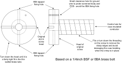
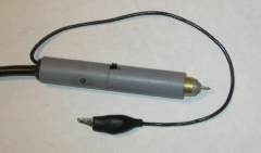
4. Homemade Scope Probe
I have made a final version of the prototype switchable attenuator probe above using some parts from an old faulty scope probe and some locally sourced materials. The photos below show a part assembled and fully assembled probe. The metal body is thin walled 11mm diameter brass tubing which was specifically chosen to fit some grey plastic water pipe already in stock. The cable clamp is made from a large brass bolt turned down to fit the brass tube, drilled through the centre to clear the insulated centre conductor and drilled and tapped for two 8BA fixings and an outer brass tube crimp.
The coaxial cable is 1m of RG62 which has an impedance of 93ohm and a low capacitance per unit length. The switch selects 1:1 and 10:1 attenuation and the compensation trimmer is adjusted for a best square wave display as with conventional attenuator probes.
This probe is specifically intended for use in measuring signals in very high impedance tuned circuits up to about 30MHz.
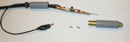
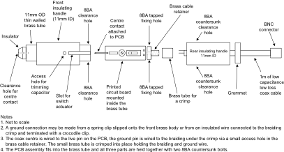
The drawing to the lower right shows an exploded view of the scope probe using the circuit in item 2 above. A more detailed drawing of the coax retainer is shown lower left. Dimensions have not been provided as these will depend on the materials that are locally available. To reduce the inherent stray capacitance in the probe head, a low height slide switch and the compensation trimmer from an old scope probe was used. The printed circuit board, which is slightly off centre to enable the probe contact to be in the centre and to accommodate the height of the switch, had to be filed to provide a snug fit in the brass tube. The final results are shown below.
|
Probe not connected |
Probe connected and set to 10:1 |
Probe connected and set to 1:1 |
||||
|
Frequency MHz |
Unloaded Q |
Tuning Capacitance |
Loaded Q |
Probe Capacitance |
Loaded Q |
Probe Capacitance |
|
1.6 |
98 |
100p |
94 |
9.2p |
92 |
51p |
|
7.2 |
112 |
100p |
106 |
9.2p |
100 |
52p |
|
22.3 |
134 |
100p |
120 |
10p |
Not measured |
|
|
32 |
115 |
100p |
100 |
10p |
Not measured |
|
Spurious resonances in the test jig and screened cable were more apparent at 30MHz and above compared to the original prototype probe with the shorter length of RG62.
Click here to download a zip file of the PDFs of the various probe diagrams.