Simple RF Detectors
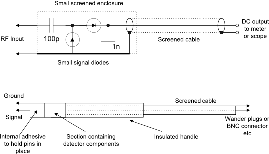
3. Passive Voltage Doubler RF Probe
A useful and simple detector probe can be built with a few low cost components and a discarded ball point plastic pen case. The diodes can be Germanium (OA47, OA90 etc) or Schottly (HP2800, HP2835, BA482, 1N5711 etc). For best results the detector section should be screened.
Any meter should be 50 or 100 microamps FSD unless some form of DC amplifier is to be used in which case it can be 1mA FSD. A 741 op-
The detector components can be wired together using a small piece of printed circuit board or Vero board for mechanical support or just mounted on the metal ground screen before insertion into the insulated handle. About 1m of any small screened or coaxial cable will be suitable to connect to the detector.
When the probe is complete and tested a small self tapping screw or small amount of adhesive should be used to retain the electronics in the insulated handle.
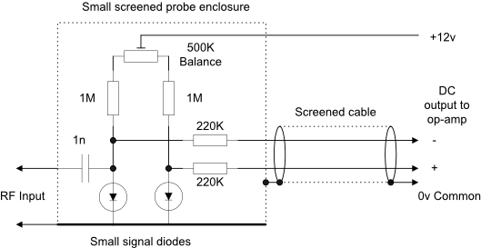
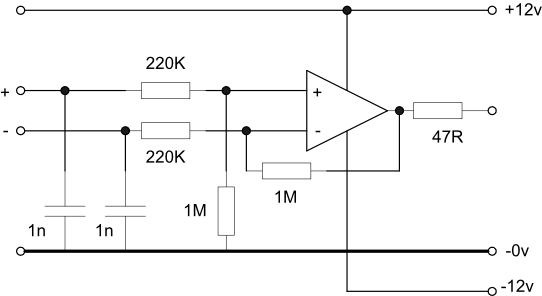
4. Active RF Probe
This probe is a little more complex than the previous ones and requires an operational amplifier to drive the meter. However, better temperature compensation and sensitivity can be obtained over a wide frequency range provided that VHF construction techniques are used -
The detector diodes should be VHF Schottky types such as HP2800, BA482 or similar. The 500K potentiometer is used to set the meter zero and should be accessible in use. A general purpose op-
To provide a 50ohm terminating impedance a 50ohm load may be constructed from two 100ohm surface mount resistors in parallel or a single 51ohm resistor as preferred. This may be preceded by an attenuator for measuring higher level signals.
The diodes may be small signal germanium or silicon although Schottly diodes are preferred.
Assemble the components on a small piece of printed circuit board. Use wire probes or a BNC coax socket at the RF input with very short leads to the PCB. The entire assembly can be housed in a small die cast box or a light-
The maximum RF input will be determined by the breakdown voltage of the detector diodes. The completed assembly should be able to detect signals down to a few millivolts if the op-
If this probe is to be used as a milliwatt meter then a small input attenuator will be required to provide a consistant 50ohms impedance at different signal levels.
The following DC amplifier has been built and tested with the dual diode detector and the results are shown in the table below. Although the resistor values are not critical and can be adjusted to obtain different gains and sensitivities the circuit must be kept balanced. The op-
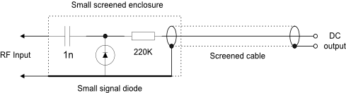
2. Passive Single rectifier RF Probe
A useful and simple detector probe can be built with a few low cost components and a discarded ball point plastic pen case. The diodes can be Germanium (OA47, OA90 etc) or Schottky (HP2800, HP2835, BA482, 1N5711 etc).
The indicator can be a high impedance analogue or digital voltmeter or an oscilloscope set to DC. A conventional moving coil meter is not appropriate because of the high value series resistor. The three components may be housed in a simple screened enclosure with small attached ‘prods’. The DC output will be positive with respect to ground.
|
RF input voltage pk- |
DC output voltage in a 1Meg load |
RF input voltage pk- |
DC output voltage in a 1Meg load |
|
680mv |
8mv |
2.3v |
520mv |
|
850mv |
20mv |
2.55v |
620mv |
|
950mv |
40mv |
2.85v |
750mv |
|
1.1v |
70mv |
3.2v |
900mv |
|
1.2v |
120mv |
3.6v |
1.05v |
|
1.3v |
160mv |
4.0v |
1.25v |
|
1.45v |
210mv |
4.5v |
1.42v |
|
1.65v |
270mv |
4.8v |
1.65v |
|
1.85v |
330mv |
5.2v |
1.85v |
|
2.15v |
440mv |
|
|
|
Input pk- |
DC output |
Input pk- |
DC output |
|
16mv |
Threshold of conduction |
460mv |
430mv |
|
34mv |
5mv |
800mv |
650mv |
|
48mv |
9.5mv |
1.3v |
1.15v |
|
64mv |
18mv |
1.6v |
1.49v |
|
100mv |
39mv |
2.2v |
2.2v |
|
150mv |
92mv |
3.2v |
3.15v |
|
220mv |
160mv |
4.4v |
4.6v |
|
310mv |
260mv |
5.0v |
5.8v |
As you can see from the table the output is not linear, especially at low levels. This means that to make a calibrated instrument, a number of scales will be required on the output meter.
|
RF input voltage pk- |
DC output voltage in a 1Meg load |
RF input voltage pk- |
DC output voltage in a 1Meg load |
|
25mv |
1mv |
800mv |
290mv |
|
50mv |
5mv |
1.25v |
410mv |
|
90mv |
11mv |
1.8v |
590mv |
|
124mv |
20mv |
2.8v |
1.0v |
|
195mv |
41mv |
3.9v |
1.45v |
|
360mv |
110mv |
5.2v |
2.15v |
|
520mv |
170mv |
|
|
With short leads, the frequency response will be flat well into the VHF bands. As can be seen there is pronounced non-
The above tests were repeated below with an OA90 germanium diode:
A detector probe has has been built using this circuit with an HP 5082-
|
Frequency MHz |
Unloaded Q |
Q with probe connected (1Meg) |
Q with probe connected (10Meg) |
Tuning capacitor pF |
Probe capacitance pF |
|
7.2 |
114 |
109 |
110 |
100 |
3.1 |
|
45 |
141 |
115 |
117 |
50 |
3.8 |
As can be seen from the results, the probe has a very small effect on the tuned circuit Q at 7.2MHz but somewhat more at 45MHz. An alternative would be an active probe using a solid state or valve device -
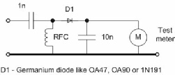
1. Passive Simple RF Detector
A useful and very simple RF detector can be built with a few low cost components and a discarded ball point plastic pen case or similar. Germanium diodes (OA47, OA90, 1N191 etc) will give the best sensitivity. The indicator can be a conventional test meter and the DC output will be positive with respect to ground.