HF Bandpass Filters
FL1 -
Check the relay specification for the minimum switching current. The above circuit will provide approximately 500uA of wetting current which may require changes depending on the relays selected. For example, Omron G5V-
The overall assembly has been configured as a daughter board containing the filters bolted onto a motherboard containing the control wiring and back emf protection diodes across the relay windings. Both boards are double sided copper clad and spaced apart by approximately 3 -
Example PCB layouts may be downloaded from here: Mother board and Daughter board
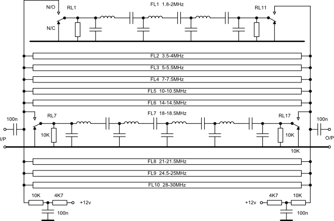
1. HF Band Filters The following circuit shows a typical set of relay switched filters for an HF bands receiver or transceiver. Full details of the relay switching controls have been omitted for clarity but these can be found on the previous page.