Solid State Circuits 19 -
This module is based on a design by AA0ZZ who very kindly put the technical and software information in the public domain (QEX July/August 2011).
The design is based on a Silicon Labs SI570 controlled by a PIC 16F88 and covers 10-
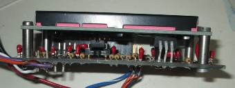
The 3.3V LDO regulator which runs barely warm is folder over on its leads and bolted to the controller PCB via a spacer. Two push buttons for user control and the shaft encoder are out of view.
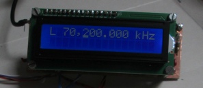
Frequency control is by a simple shaft encoder (either mechanical or optical is fine) and a menu system is accessible via the two push buttons.
A 5volt regulated DC supply is required.
Above right is a side view of the two PC boards. Tucker L762 eyelets were used in lieu of through plating to connect top and bottom copper layers together with sufficient space in the center for a component lead. If you make a hand painted board then make sure that the copper tracks to connect to the SI570 are long enough to reach under the solder pads by 1mm otherwise soldering is very difficult. I draw the IC outline to scale in pencil on the board before painting the tracks.
The current through the backlight has been increased to improve the display in daylight by decreasing the 330R resistor to 150R.
Several iterations of the software have been required and as currently released, assumes a default frequency of 10MHz for the SI570. If your SI570 has a default frequency of about 56MHz then some very minor software changes will be required.
To assemble the software you will need the free MPLAB IDE V8.92 or later package from Microchip Technology at https://www.microchip.com/mplab/embedded-
To program the 16F88 you will need a PIC programmer connected to your PC.
I have completed my tests on V5.8 of the software and am now making changes to suit my own equipment requirements. PC board changes now include contact debounce, RF filtering and the original three output lines are now configured as inputs. A new PC board layout has been completed and tested with the back light variant of the LCD display installed. An updated circuit will be posted here in due course.
A scan of my hand drawn double sided PCB layout can be downloaded from here. Make sure that the scaling is set to ‘none’ or 1:1 for printing.
The modified circuit diagram can be downloaded from here.
The SI570 manufacturer provides an individual frequency calibration value on chip to minimise frequency errors and the software has a manually selectable calibration routine to read this value and recalculate the lookup tables used during normal operation. Before this routine was run the typical error was around 3KHz at 60MHz and after it was run the error was typically 150Hz at 60MHz.