SB-
Summary of Changes
To achieve full break-
The aerial changeover relay was removed and replaced with a cathode follower T-
The bandswitch was rebuilt to add an extra position for top band and an extra position marked on the front panel using white Letraset.
A grid block control system was installed using the -
A multiway socket was added to the rear panel to enable PTT control and CW monitor lines to connect to the a matching but completely rebuilt SB301 receiver.
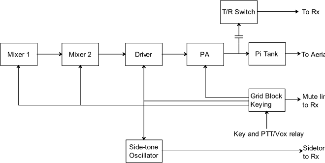
The following block diagram shows the revised control system:
The changes mean that I can listen through the key-
There is no intention of doing any further modifications as an SB-
See Valve Circuits 3 for more information on grid block keying and T/R switches.