R7 Vertical...Maintenance and Repair
Home
Links
Contact
Information
Copyright © 1995 - 2021 John Tait All rights reserved.
The Cushcraft R5 and R7
verticals are favourites of mine, ever since Alex EI6AG,
my friend and "Elmer" for many years, gave me a present of a
set of faulty R7 traps.. It
was fun to repair the traps, and then "homebrew" the rest of
the antenna, including the matching box..
Many thanks to Joe
Reisert W1JR, whose advice helped me get it up and running. Thanks
also to Dave Moore EI4BZ, who allowed me to dissect his R5 "Black
Box" in the name of Science...!
I like the idea of the
1/2 w/l radiator, as against the usual 1/4 w/l fed against ground.. My
"homebrew" version works extremely well, and I use it
as my "standby" and "reference" antenna.
(Circuit diagram
of the matchbox)
There are a few
problems which arise from time to time in older units..
especially in wet and windy areas.. or close to the Sea.
Varying,
or high SWR on one or two bands.
This is usually
caused by bad connections on the trap clamping arms. They should be
carefully loosened, moved aside, and the contact area cleaned with
steel wool. When clean, the area should be greased with Vaseline, or
one of those dissimilar metal contact greases used by the electrical
power utilities.
If this treatment
doesn't work, and you still have high SWR one band, Then you have a
....
Faulty trap.
Traps usually go
faulty because the heatshrink seal on the trap fails, and water gets
inside the coaxial "trombone" capacitors on the traps. If
the inside of the tube gets wet,
this changes the dielectric constant of the capacitor, and the value
of the capacitor changes, thus moving the resonant frequency of the
trap. You will find that the SWR minimum point has moved, and
normal adjustment will not bring it back on frequency.
If this
situation is not corrected, eventually the capacitor will short out,
especially if you're running high power..
Running high
power into a bad SWR can eventually destroy the matching unit..!!!!
More on that later...
To repair the
trap, you must carefully note the length that the capacitor
"rod" extends out of the "Tube". The rod can slide
in and out of the tube, and is one plate of the capacitor, so you need
to get it back the way it was before you dismantled it...!
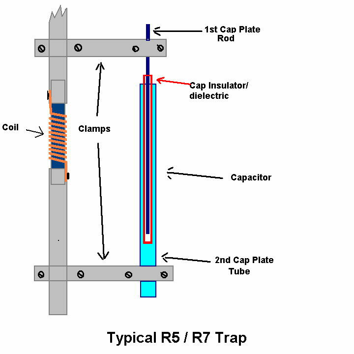
Carefully dismantle this
capacitor. Dry and clean all of the components, and reassemble.
Re-seal the tube with "self-amalgamating" tape.
All should now be well again...
If the insulator tubing is badly
damaged, you should go to Gerry
VE6LB's page . He has a great method of repairing
traps using Hot Melt Glue. When you see the original damaged
trap, you'll be amazed that it could ever be fixed.. Well done Gerry!
If you have high SWR on ALL bands, then
you probably have a
Faulty
Matching Unit..
A - Matching
capacitors. These are a pair of 86pF in series, to give an
actual value of 40/50pF. These can, and do go open-circuit. Replace
them with a single HIGH CURRENT type (doorknob)
of 50pF if you can. ( I use three 15pF caps in parallel)
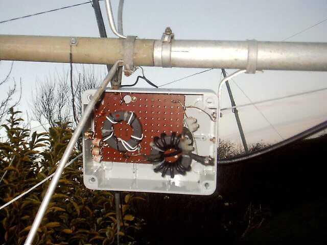
B - 4:1 BALUN transformer.
These can actually disintegrate with bad SWR and high power...Ouch !!
Replace with an Amidon Iron Dust core T200-2 wound as in pic above.
Or with a Q1 material Ferrite core ( FT240-61) wound
with 6 bifiliar turns (as against 11 in the pic above).
C - This antenna, being
asymetrically fed, needs an effective Choke Balun to keep RF
from the exterior of your feedline. This
should not give any trouble...But if it does, an Iron Dust Core will NOT
work here.. I use a ferrite core, Q1 material.
D
- Make sure that all hardware connections are clean and secure
E - Moisture release vent.
F - Feed point (SO239)
G - PC board .
H - RF choke effectively DC
grounds the radiator to help prevent static electricity from entering
your shack. If everything else looks OK in the unit, and the SWR is
high on ALL bands.. Disconnect this choke. After heavy static,
turns on the choke can become shorted. This damage may be impossible
to see with the naked eye.
( Pic of my
homebrew R7 matchbox.. Not as pretty as the commercial one, but works
just as well! )
Take a look at the
brilliant rebuild job that
Darren G0WCW did on a wrecked R5 Match box. It's now working
perfectly again..
Measure your trap frequencies..
It's a good idea to take a note of your trap's
frequencies, in case you need to repair one in the future..
I measured my traps under the following
conditions..
Disconnect Each trap unit from the rest of the
antenna.
My measurements were taken with the trap unit
resting on a large cardboard box, well away from all metallic
objects..
I used my MFJ 259 analyser with a piece of insulated
wire , configured as a single loop around the end of the coil on the
trap assembly.
Vary the frequency on the MFJ until a strong dip is
seen..
Now move the single turn link away from the end of
the coil, while retuning for the dip, until a very shallow dip
(least loading on the trap) is seen, and take note of the frequency
read out.
Make sure that you do not touch any part of the trap
while taking the reading.
These readings, though not strictly accurate because
of the loading effect of the attached tubing and hardware, are very
useful.
Make a note of your readings for each band, and keep them
safe. If, in the future, you need to readjust a trap, then you can
set it to the original reading.
I obtained the following readings from my R7...
TV1 10m
26.5 mHz
12m 23.2
TV2 15m
20.05
TV3 17m
17.5
TV4 20m
12.85
TV5 30m
9.73
You can see from these readings, how the hardware
loads the traps, and gives a lower frequency reading than the
actual.
Ken KA1VMR, who was very helpful to me, told me that
Cushcraft, when making these traps, used a Signal generator and
oscilloscope to set up the traps on the following frequencies..
TV1 10m
28 mHz
12m 24
TV2 15m 21.2
TV3 17m
18.11
TV4 20m
14.47
TV5 30m 10.25
Any manuals that you may require for
these antennae are available in .PDF format on the web.
Home
Links
Contact
Information
Copyright © 1995 - 2021 John Tait All rights reserved.
All pages and content there-in, are the intellectual property of the
author, and protected by law.
All pages and content, are subject to change at any time, without notice.