PICs are single-chip microcontrollers which can be used for many purposes. WinPic can program some of these devices, using a simple piece of hardware connected to the serial port (COM1..COM4) or the parallel port (LPT1 or LPT2) of a PC. There once was a simple DOS-program called "PIP-02" to do this, but that program did not work properly on my PC under windows so I wrote my own. Thanks to my contributors, WinPic now supports a large variety of PICs with different programming algorithms. Programmable devices are listed on the Features page.
Note that most programming adapters supported by WinPic do not meet Microchip's
requirements for a "production grade" programmer. If you think you need a
production grade programmer (which can verify the PIC at different voltages),
look here.
If you're interested in developing PIC firmware, buy an interface like the PicKit 2 or 3
(not a clone). PicKit 3 is not the most reliable development tool, but it can also be used
as an in-circuit debugger, at least for more recent PIC devices.
Thus, except for trivial 'ad-hoc' PIC- and dsPIC-projects there is no need for programs like
WinPic anymore. The WinPic author gave up developing PIC firmware, since there
are more powerful devices like Cortex-M supported by a wealth of free development systems.
Consider this: For the price of ONE "PicKit 3", you could buy FOUR Cortex-M4 development boards,
with onboard debugger. Or two Raspberry Pi's, but that's a different breed...
and even Cortex-M0 devices are available in breadboard-friendly 28 pin DIL package,
and (sorry having to say this) any ARM/Cortex development toolchain is more mature than
the C compilers by Microchip (which, in the "free" editions, produce anything but good code).
Ok, back to the subject: WinPic lets you ...
Keep in mind that this program is still far from being "professional" software ! Last not least because this program is freeware, the entire risk of its use is with you - read the disclaimer if you haven't yet.
Check for an update on the author's homepage.
Note: Meanwhile there are other programs called "WinPic" on the web.
If you look for an update, search the net for "WinPic" AND "DL4YHF" to find
this one !
Program : WinPic - a PIC programmer for Windows
Revision Date: 2006-11-02 (YYYY-MM-DD)
Author: Wolfgang Buescher (DL4YHF) and contributors, see
"About"-box
Sourcecode: available on the author's
homepage
Homepage: see links at the end
of this document
Email: can be found on the homepage (subject to change /
spambots keep off !)
The program requires a simple programming interface for the serial port. For FLASH-based PICs like the 16F84, the hardware is very simple, for EPROM-based devices like the 16C61 two additional transistors are required.
Supported devices are (AT LEAST...) :
WARNING ! The specification for EPROM-based PICs requires a precise timing which is hard to realize under Windows. Don't let other programs run in the background when programming EPROM-based PICs (16C7xx), and use the fastest PC available. This reduces the risk that windows takes the CPU away for other tasks too long, but is no real cure.
If you don't find "your" PIC in the list of supported devices, you may add support for it as described here .
You will need the following to use "WinPic":
If you have an interface which is not directly supported : the programmer can be customized for other programming adapters via INI-file.
Since WinPic is now distributed with an automatic installer, you simply select where it shall be installed (after reading and agreeing to the disclaimer). After installation, you should see the following files :
?\WinPic\devices\*.dev ....... subdirectory with device definitions borrowed from MPLAB
?\WinPic\html\*.* ............ WinPic's online manual in HTML format
?\WinPic\interfaces\*.ini .... custom interface definitions ("programmers")
?\WinPic\translations\*.txt... translations of the WinPic GUI into other languages
?\WinPic\WinPic.exe .......... the executable
?\WinPic\smport.sys,smport.vxd, porttalk.sys ..... the optional port access drivers(*)
?\WinPic\devices.ini ........ file telling WinPic how to program some new PIC devices
?\WinPic\readme.txt ......... disclaimer, short info, revision history
(*) earlier versions of WinPic did not work with the port drivers. Click here for details.
A few other notes about the installation and translations can be found in the file README.TXT. In case of trouble, please read the FAQ list.
If you get some strange error messages when trying to start the program for the first time (perhaps missing DLLs), check the author's homepage for more information.
If you use WinPic to program PIC18F or dsPICs, read this chapter in the FAQ's - it shows you how to tweak WinPic for maximum speed for "simple" PIC programmers (works best with the PortTalk driver). To use PortTalk without an administrator account under Windows XP, you can install PortTalk permanently on your system as explained here.
The main window of the Pic Programmer consists of several tabsheets:
 If you use WinPic for programming with an integrated development
system (like MPLAB), and frequently program your PIC for testing purposes,
use the small tool window. It remains open on top of any window, even if
it doesn't have the focus, and even if WinPic's main window is minimized.
You can reload the new file and program it with a single mouseclick on the
"Reload & Program"-button. The name is the last file you selected for
loading from WinPic's file menu. The filename is shown below the button.
If you use WinPic for programming with an integrated development
system (like MPLAB), and frequently program your PIC for testing purposes,
use the small tool window. It remains open on top of any window, even if
it doesn't have the focus, and even if WinPic's main window is minimized.
You can reload the new file and program it with a single mouseclick on the
"Reload & Program"-button. The name is the last file you selected for
loading from WinPic's file menu. The filename is shown below the button.
To open the Tool window, select "Tools"..."Show Tool Window" from the main window. To switch back to the main window, use the ">>" button in the lower right corner.
During programming, a progress indicator and the current status is also displayed in the tool window. If programming is finished successfully, the tool window turns green, in case of errors it turns red.
This is the usual operation sequence in interactive mode (for command-line mode, see another chapter):
You don't have to erase the PIC before programming, the software will do that automatically.
The software will always show the success or errors of all actions. If there is an error message in the status line at the bottom of the programmer's window, change to the "message"-tab where you see a complete list of all errors (with more infos about the cause of the error, etc).
Also the configuration word and the initial DATA EEPROM will be programmed, if the HEX-file you loaded contains data in the equivalent memory ranges. For more information look into Microchip's data sheets.
You can terminate the programming loop anytime by pressing the ESCAPE key - this may save a few seconds if you discover you have not inserted a PIC in the socket.
After programming, reading, or successfully verifying the PIC device, the programmer (or ICSP-adapter) can be completely disconnected from the target for test code runs. You need an interface like Johan Bodin's "PIP-84 V2" which has additional hardware to disconnect all lines between the PC (parallel port) and the target device. The "disconnect control signal" is D7 on the LPT port, explained in the appendix.
To program a whole bunch of devices with the same data, load a hex file once, then select "Tools" ... "Start Batch Programming" from WinPic's main menu. Once in this mode, the following steps are repeated over and over until you stop the batch mode (by pressing ESCAPE or via menu).
You may call WinPic from a batch file, or an integrated development environment to do an automated job without any user intervention. For example, you can tell WinPic to load a program from a hexfile, write it into the target device, and terminate itself afterwards.
The following list shows all command line parameters which are accepted:
Note: The sequence is no longer important (this was different
in older releases of WinPic, where the file name had to be specified before
the "/p"-command etc).
The command-line driven operation can be cancelled by pressing ESCAPE. The main menu will be enabled anyway. Selecting certain menu items also cancels evaluating the command line.
Some commandline examples:
winpic keyer1.hex /p /q
winpic /nodelay c:\pic\my_src\keyer1.hex /p /q
winpic /overwrite /r "readout.hex" /q
The interface type must be set once after program installation, then forget about it - because WinPicPr saves the interface type (along with other settings) in an INI file. You can select the interface type from a list on the "Interface" sheet.
Depending on the interface type, you may also select COM1..COM4 or LPT1..LPT2
(see notes on the LPT port in the appendix).
The default interface type is the "COM84" interface which is connected to
the serial port. If you have a (simple) programmer for the parallel port
which is not listed, you can add support for
your own interface by adding a few lines to the SETTINGS.INI files as
described in the appendix.
Note: For interface on the LPT port, WinPic must use one of the
port access drivers (SMPORT or PortTalk). Since
November 2006, it does not need such a port driver for the serial port. In
fact, WinPic may work with USB<->RS-232 converters, too.
The programmer does a crude "interface test" at program start to check if the interface is installed. This is done simply by setting the 'data output' and reading back the signal from the 'data input' (while the Vdd voltage turned on for a short while). If an error is reported, either the interface is not connected properly, or power turned off, or wrong port selected.
 To solve interface
problems, there is a simple 'Interface Test' option available where you can
control all signals yourself by setting or clearing the checkmarks "Vpp",
"Vdd", "Clock", "Data" (etc) and check the voltages. The actual state of
the "Data In" line (from PIC to PC) is displayed as "Data In = X", where
X resembles the logical state of the PIC's RB7 pin (it may be inverted by
the programmer hardware).
To solve interface
problems, there is a simple 'Interface Test' option available where you can
control all signals yourself by setting or clearing the checkmarks "Vpp",
"Vdd", "Clock", "Data" (etc) and check the voltages. The actual state of
the "Data In" line (from PIC to PC) is displayed as "Data In = X", where
X resembles the logical state of the PIC's RB7 pin (it may be inverted by
the programmer hardware).
Signals not supported by the selected programmer appear disabled in the
checkmarks (for example, "Clock Enable" and "Data Enable" which are only
used in Microchip's "AN589" programmer).
A crude interface test can be performed by clicking the "Initialize !" button
on the Interface sheet. The result of the interface test can be viewed on
the Messages sheet (the last message is displayed in the status line, clicking
it will switch to the Message sheet with an error history).
 Beware that different PICs require different programming- and supply voltages these days
(not as in the 'old days' where Vpp = 12 V and Vdd = 5 V was always safe..).
Beware that different PICs require different programming- and supply voltages these days
(not as in the 'old days' where Vpp = 12 V and Vdd = 5 V was always safe..).
If WinPic has access to Microchip's dev-file for the selected PIC, it will know
which voltages can be used, but with none of the 'simple' programming adapters
it can set the required voltages itself ! (This is what justifies the higher
price of the 'commercial' adapters by Microchip: They have programmable supplies
for Vpp and Vdd).
So it is your duty to set the correct programming- and supply voltage for your PIC.
The circuit diagram of the author's 'Serial Programmer V2
shows how this can be achieved by connecting lower-voltage Zener diodes parallel to the
always present 12- and 5-V diodes for Vpp and Vdd, respectively.
Some of the interfaces which are supported by WinPic are:
To tweak WinPic for maximum speed, you may try to optimize the following parameters on the Interface tab (the default settings are reasonably slow and reliable):
These additional delays can be used for "slow" interfaces, especially when
the PortTalk driver is used instead of SMPORT. More details on that
here.
For a sluggish USB <-> serial port interface, the 'extra delay' values had to be set
to at least 1000 microseconds, for reasons explained here.
9-pole "D-sub" connector, male, "DTE" connector side
| Pin Number on 9-pin DTE (PC) |
Signal Name on DTE (PC) |
Direction from the DTE's (PC's) point of view |
For 'COM84' interface, used as |
1 |
DCD |
input |
|
2 |
RxD |
input |
|
3 |
TxD |
output |
Vpp control (+12 V) |
4 |
DTR |
output |
data from PC to PIC |
5 |
GND |
signal ground |
|
6 |
DSR |
input |
clock feedback from PIC to PC |
7 |
RTS |
output |
clock from PC to PIC |
8 |
CTS |
input |
data from PIC to PC |
9 |
RI |
input |
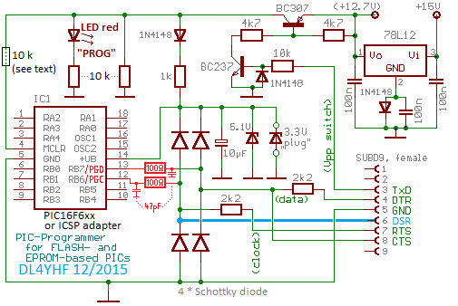
For dsPIC and PIC18, add the components for 'PGD / PGC filtering'
shown in red colour. These lowpass filters shall reduce crosstalk between PGD (data) and PGC (clock).
They must be located as close to the PIC as possible; for in-circuit programming, locate them on the target board (not on the programming interface).
A 'strong' Vpp source as shown in the circuit above is only required for very old chips, with EPROM (not FLASH) memory.
If the programming adapter only needs to support Flash-based PICs, the Vpp line only needs to source fractions of a milliampere.
To reduce the risk of accidentally ruining your target board (when not 13-Volt-tolerant circuitry is connected to the alternate
function of MCLR/Vpp), add a series resistor before the MCLR input (close to the PIC).
To program PICs which require lower programming- or supply-voltage, use additional Zener diodes to keep all voltages
in the range specified in your PIC's datasheet. Beware, some devices are killed by Vdd = 5 V, others are killed by Vpp = 12 V !
With the 'clock feedback', the programmer will always use the maximum speed, as permitted by the USB adapter,
and it's not neccessary to fiddle around with the extra delays on WinPic's Interface tab any longer.
The speed can be tested by clocking out a long stream of 1,0,1,0,... (there's a button to start this test on the 'Interface' tab).
Shown below is the test result using a 'Prolific' USB adapter. Each USB transaction obviously consumes one millisecond,
and because each bit clock cycle requires two transactions (one to set CLOCK=high and shift out DATA, one to set CLOCK=low again),
it takes two milliseconds per "serial bit", and since a single word in the PIC's code memory requires approximately 28 cycles
(for the PIC16F628, includes sending the 'increment address' command), programming an entire PIC with this adapter consumes
about 125 seconds (!). "That's not a bug, but a feature" (of this USB 1.1 adapter).
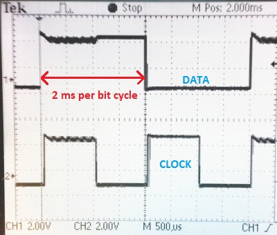
DATA and CLOCK waveform, measured when using an unlabelled
'Prolific USB-to-Serial Comm Port' adapter. 1 ms per half bit cycle,
resulting in a total time to read or program a PIC16F628 of 125 seconds !
For comparison, on a PC with a 'real' serial port (Thinkpad X61s with docking station), with the same PIC, same configuraton,
programming or reading an entire PIC16F628 finished in less than 5 seconds.
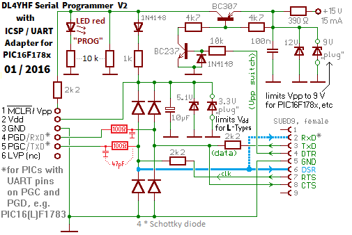
DL4YHF Serial Programmer V2, can be used to connect the
target to a terminal program (besides being an ICSP adapter).
| PC side of 'DL4YHF Serial Programmer V2' | Connect 6-pin ICSP adapter to ... | |||||
|---|---|---|---|---|---|---|
| Pin Number on 9-pin DTE (PC) |
Signal Name on DTE (PC) |
Direction | Usage | ICSP pin | Pin on SPDIP-28 PIC16F1782/3 |
Pin on SPDIP-28 dsPIC30F3013 |
1 |
DCD |
? → PC |
- |
|||
2 |
RxD |
PIC → PC |
terminal: PIC-TXD |
|||
3 |
TxD |
PIC → PC |
ICSP: write data, |
|||
4 |
DTR |
PIC → PC |
Vpp+MCLR control |
1 |
1 (Vpp/MCLR/RE3) max 9 Volt ! |
1 (Vpp/MCLR/RE3) max 13 Volt ! |
5 |
GND |
PIC ↔ PC |
signal ground | 3 |
8, 19 (connect both!) | 8, 19, 27 (connect all, including AVss) |
6 |
DSR |
PIC → PC |
ICSP: clock feedback |
5 |
27 (ICSPCLK/RB6) | 18 (PGC/.../RF2) |
7 |
RTS |
PIC ← PC |
ICSP: clock |
|||
8 |
CTS |
PIC → PC |
ICSP: read data |
4 |
28 (ICSPDAT/RB7) | 17 (PGD/.../RF3) |
9 |
RI |
? → PC |
- |
|||
PIC supply voltage |
2 |
20 (Vdd) "L": max 3.6 V ! |
13, 20, 28 (connect all, incl. AVdd, max 5 V) |
|||
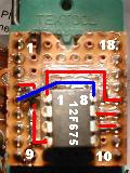
The following schematic diagram is for a simple "COM84-compatible" PIC programmer on the serial port (COM1 or COM2). You should build a more advanced programmer ! Check the voltage at the serial interface before deciding to build this extremely simple programmer. The 'voltage boost' via R5 may be required if the 'high-'voltage at the TXD pin is too low for the PIC to enter programming mode. If you need a circuit which also programs EPROM-based PICs, or want something with a more reliable 'programming'-voltage, look here. If you need a circuit which works without extra supply (under all conditions), try the JDM programmer type 2 (TWO! ... search the net for "JDM PIC-programmer 2" to find the schematics; it is supported by WinPic too, and -unlike other "simple's"- the JDM 2 works for PIC18Fxxx and even dsPICs.)
This 'very simple' programmer is only for certain FLASH-based PICs. Again, I strongly recommend not to use it, however ... :
The disadvantage of this programmer is the programming voltage (which should be about 12.7V on pin 4 of a PIC16F84) taken directly from the serial interface. Some interfaces only put out about +8V maximum, and that is definitely too low for programming. You may try to connect R5 and an "auxiliary" 12V source to boost the programming voltage a litte. The "next better programmer" uses two switching transistors for the programming voltage. To program 8-pin-PICs like the 12F675 you need an adapter or an extra socket on the board.
The clamping diodes D3, D4, D5, D6 limit the voltage from the RS-232 interface to avoid latch-up of the PIC. There are some other "extra simple" circuits out there which do not use any protection for the PIC, but you should invest a few pennies/cents for these diodes. A schottky diode (e.g. BAT46, 1N5817, PMEG2005) must be used, not an ordinary silicon diode (like the ancient 1N4148) because its forward voltage is less than 500mV so we know the 'limiting' current flows through the diodes, not through the precious PIC !
When tested with a 16F877 (and an adapter socket), this interface failed, while programming an old-fashioned 16F84 worked. This is why I strongly recommend to use the programmer described in the next chapter, or an even better one...
Some years ago, a programmer called "AllPic2" (or "AllPic02") appeared in several magazines. It is compatible to "COM84", and to the two interfaces shown in this document, but very often you will find it has :
To program EPROM-based PICs (like the 16C61/16C71), use this interface which
delivers more current into 'Vpp' (programming voltage, applied to 'MCLR'
= PIN 4 of most 18-pin PICs). The circuit shown below was slightly modified
in 2015-12, so if you build one from scratch, consider using this circuit instead
(which contains the PGD & PGC filters mentioned further below).
If a precise (regulated) 12.7 V DC power supply is available, the voltage regulator (78L12, with D7, C2..C3) is not needed.
The function of the clamping diodes (D3..D6) is explained somewhere else.
To program 8-pin-PICs like the 12F675 you need an
adapter or an extra socket on the board.
To program some 28-pin PICs like the 16F876 you need
another adapter, and
yet another adapter for the 28-pin dsPIC
family.
If you experience problems with dsPIC30Fxxxx, PIC18Fxxxx, or other unexplainable
problems which seem to be related to the length of the interface cable, read
this important note on PGD & PGC
filtering (avoid coupling between clock- and data line).
See also: PIC programmers for the parallel port
The tab sheet "Device, Config" is used to select a PIC device and modify the configuration word. It is highly recommended to embed the configuration word in the HEX file (so you don't have to set the proper config word yourself), but you may want to check or modify the configuration word yourself after loading the HEX file.
In the combo box labelled "Part:", you select the PIC device which shall be programmed.
The contents of the table of configuration bits depend on the selected device type, and on the device definition file. Only for "old" devices (PIC16F family), WinPic contains built-in configuration bit definitions. For newer chips, especially the PIC18F and dsPIC30F family, the configuration bit info should be read from one of Microchip's device definition files (*.dev). WinPic expects the DEV-files in a certain directory - see this textfile for more information. The DEV-files are Microchip's own property, and due to the MPLAB terms of use I cannot distribute them with WinPic. But you will have them on your harddisk after installing MPLAB !
Below are some bits (and bit groups) in the configuration
memory which WinPic can handle even if there is no dev-file for the currently
selected device:
If a PIC is not directly supported by the programmer, set the PIC type ("Part") to "unknown". Then all checkmarks for the options in the configuration word are disabled, but the Config Word can still be edited as a hexadecimal value. See 'unsupported PICs' for more information. Note: Other areas in the chip's configuration memory may be shown on the Configuration Memory tab (for example the chip's ID locations, backup oscillator calibration value, etc)
Device properties:
Shows the size of the program memory and the data EEPROM memory. If the PIC type is set to "unknown", some device properties like code- and data memory size can be edited. Instead of using the "unknown PIC" option, it's better to add support for your new PIC device as explained in the appendix.
A user may store identification information (ID) in a number of programmable cells, often four or seven bits per location. These locations are mapped to addresses 0x2000 to 0x2003 (that's where you may find them in a HEX file; applies to "14-bit core"; for other cores the addresses are totally different). In contrast to the code memory, the ID locations can be read unscrambled even if the PIC is protected.
In MPASM (the assembler from microchip), there is the __idlocs command (with two underscores) to set these bits, but only the lower 4 bits in every location. The __idlocs command bundles 4 * 4 bits in a single 32-bit value, presumably because older PICs only had 4 usable bits per ID location. But the 12F675 for example has seven bits per location !
With WinPic, you can read / modify / write the ID locations (all bits). If ID location data are contained in a HEX file, they will be loaded and displayed also. WinPic does not display the data in MPASM's 4*4-bit-format, it uses a table where all bits are displayed in binary form. You can edit the contents of the grid table. After doing so, click the "Apply edits" button under the table. Clicking this button copies the table contents into an internal buffer, but does not program them into the PIC immediately - the ID locations will be programmed together with the other programmable parts in a PIC.
The "Device ID word" can be used to identify a chip after reading the PIC. This 14-bit word is mapped to address 0x2006, but not all PICs seem to have it (a test with an old 16F84 always returned 0x3FFF as device ID). The lower 4 or 5 bits may contain the PIC's revision number in some devices. WinPic tries to decode the device ID word and shows the result on the "ID locations" tab. If there is a conflict between the selected PIC device and the readout ID word, the Device ID display turns red. If WinPic cannot find a match for the device ID of the new chip, you may add a new entry to the device database as explained here (don't forget to set the parameter "DeviceIdValue" to the new chip's device ID).
When new PIC devices with new cells in the configuration memory area (0x2000..0x203F) turned up, the appearance of the Configuration Memory tab was modified. Now, after setting the checkmark "show ALL locations", the entire memory area may be displayed, whether it's implemented in the PIC or not.
The "Config Memory" tab may also show the contents of some other special function registers which did not fit on the "Configuration Bits" tab. For example, you will find the PIC10F20x's Backup OSCCAL Value in this table.
Because it is entirely unknown how many (and which) cells will be used in the configuration memory in future devices, WinPic's device table now contains information of all really "implemented" cells. More about this in the chapter about the file DEVICES.INI, which describes how to add support for future devices.
On the "Options" tab you can modify the behaviour of the PIC programmer (software), how WinPic accesses the parallel or serial port, and modify some other parameters which may need 'tweaking' for various reasons. Here are just some of them:
By default, WinPic does NOT try to access the registers of the serial port directly, because all of the port drivers mentioned below caused problems with other programs (noteably Microsoft's "Windows Defender" didn't like the SMPORT driver). So try to use WinPic without these drivers, if possible. Only if your PIC-programmer is connected to the parallel port (LPT), you must use one of the drivers below, because the Windows API doesn't have the necessary functions for that port. This worked ok under most Windows versions so far, but it may be painfully slow when programming larger PICs because every single port access required a driver call (from ring 3 to ring 0, if that means anything to you..). Now there is the option to select how WinPic accesses the I/O-ports. This is on the 'Options' tab:
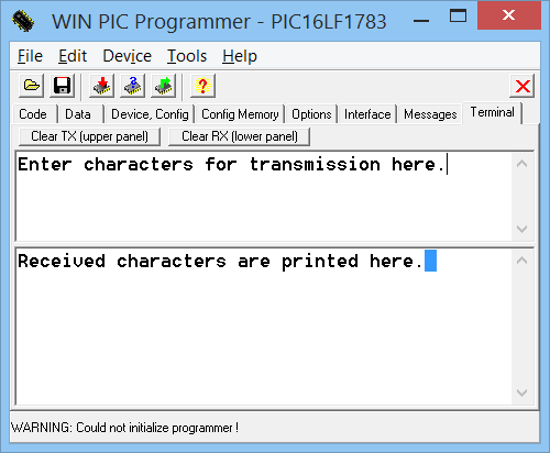
Since the handshake lines are usually occupied for in-circuit programming, there is no flow control.
The serial data format is always 8-N-1 (eight data bits, no parity, one stop bit),
the serial baudrate can be entered on the Interface tab.
One of the 'simple' ICSP adapters which can als be used to connect the terminal to the target
is the 'DL4YHF Serial Programmer V2'. It uses
a nice feature of some PICs (e.g. PIC16F1782/3), which can reconfigure
the ICSP-clock and -data' line as UART I/O lines.
So after programming a new firmware, you can leave this ICSP adapter in place, and use it
for "printf-style" debugging. Of course, this is not a replacement for a real in-circuit debugger.
See also (more common these days) : PIC programmers for the serial port
Using a simple PIC programmer at the parallel port can cause headaches under
certain Windows versions. First of all, you must select one of the
port access drivers mentioned above, because the
Windows API (application interface) doesn't have suitable functions for the
parallel port. Even worse: Sometimes the printer driver (or whatever?) accesses
the port though WinPic tries to occupy the port itself. This somehow depends
on the signal used to read back the data from the PIC. Especially the PAPER
OUT signal seems to attact Window's attention .. and should be avoided for
this reason. I did not check if removing all printer drivers can help, if
you know more please let me know.
WARNING ! Because Windows sometimes fools around with the parallel port, and we don't know the state of the parallel port before starting the programmer, first connect the programmer with the PC, then turn the PC on, start the programmer, and insert the PIC into the socket (or connect the ICSP cable) shortly before programming ! If you get an error message from WinPic saying "Windows fooled around with the parallel port bits", read this .
However, it may be possible to use a few -in the days of DOS widely
used- interfaces. Supported (but not all tested) are the following
interfaces, along with their major differences.
If your programmer shall support dsPIC and PIC18F too, read this note on
PGC- and PGD filtering.
(2004-01-26: Modified the TAIT-programmer settings after I found some more
schematics on the web)
| Interface type | Data PC->PIC | Clock PC->PIC | Data PIC->PC | Vpp Control | Vdd Control | Remarks |
| PIC FLASH programmer V1 (SM6LKM, 2002-10-01) |
D2, not inverted |
D3, not inverted |
ACK, inverted |
D4, inverted (L=Vpp on) |
D0, not inv. (H= Vdd on) |
ICSP adapter with D7 = ICSP disconn(*) |
| PIP84 (by SM6LKM) |
D2, not inverted |
D3, not inverted |
PAPER,inverted | D4, inverted (L=Vpp on) |
D0, inverted (L= Vdd on) |
D1=green LED D7=ICSP disconnect |
| PIP84 (alternative) |
D2, not inverted |
D3, not inverted |
ACK,inverted | D4,inverted | D0,inverted | D1=green LED D7=ICSP disconnect |
| Tait, 7406, 4066 |
D0, inverted |
D1, inverted |
ACK, inverted |
D3, inverted |
D2, inverted |
7406=inverter 4066=switches |
| Tait, 7407, 4066 |
D0, not inverted |
D1, not inverted |
ACK, not inverted |
D3, not inverted |
D2, not inverted |
7407=non- inverting driver |
| Tait, 7406, PNP |
D0, inverted |
D1, inverted |
ACK, inverted |
D3, not inverted |
D2, not inverted |
7406=inverter, + PNP-transistor |
| Tait, 7407, PNP |
D0, not inverted |
D1, not inverted |
ACK, not inverted |
D3, inverted |
D2, inverted |
David Tait's "classic" design |
| Microchip "AN 589" |
D0 | D1 | ACK | D3 | none (always on) |
D2=data tristate, D5=clock tristate, D4=Pull MCLR down |
| Pin Nr | Signal | token name in interface definition file |
Direction |
Description (usual function) |
| 1 | /STROBE | str | PC->printer | 'Byte clock' |
| 2 | D0 | D0 | PC->printer | Centronics Data |
| 3 | D1 | D1 | PC->printer | Centronics Data |
| 4...8 | ... | ... | PC->printer | Centronics Data |
| 9 | D7 | D7 | PC->printer | Centronics Data |
| 10 | /ACK | ack | printer->PC | Acknowledge |
| 11 | BUSY | bsy | printer->PC | Busy or Error |
| 12 | PAPER | pap | printer->PC | high=printer ran out of paper |
| 13 | SELECTED | sld | printer->PC | high=printer is on-line |
| 14 | /ALF | alf | PC->printer | automatic line feed |
| 15 | /ERROR | err | printer->PC | out of paper, error, offline |
| 16 | /INIT | ini | PC->printer | resets the printer |
| 17 | /PRINTER SEL | psl | PC->printer | low = select printer |
| 18..25 | GROUND | - | connect ALL LINES to ground |
Sometimes (especially under Windows XP) you may get a sloppy error message from WinPic telling you that "Windows fooled around with the parallel port". The reason for this may be a scanner driver, printer driver, or the plug-and-play hardware detection which permanently polls the port for new devices. Of course, this will spoil the operation of a PIC programmer connected to the parallel port !
The problem could sometimes be fixed by adding (or modifying) the following key in the windows registry :
[HKEY_LOCAL_MACHINE\SYSTEM\CurrentControlSet\Services\Parport\Parameters]
"DisableWarmPoll"=dword:00000001
Search the web for "Jan's Parallel Port FAQ"; the site contains details about
this registry hack.
Caution: Only modify the registry if you know what you're doing ;-)
If your (simple) programmer for the parallel or serial port is not listed on the 'interface' tab, here's what to do (besides the option to write a plugin for it) :
[ProgrammerControlLines]
with the following entries ... some of them optional, only a few are mandatory, marked with "m"=mandatory:
DataIn=ctsVppOnOff=txdClockOut=rtsDataOut=dtrDataOutWhileReading=1ClkEnable=ncThe function token in the definition file is followed by a "=" character, and a symbolic definition for the control signal which is used. This can be any of the centronics data lines, inverted (LOW-active) or not inverted (HIGH-active). "Active" must be seen from the target's point of view. If -for example- there is an inverter between the serial data output on centronics D0 and the PIC's "RB7" pin, the definition line must be
DataOut=!D0
These names can be used for control lines on the centronics port ("LPT1" or "LPT2"). Non-inverted always means active-HIGH level on the PC's output, no matter what the centronics printer specification says (signals which are inverted by the PC hardware are automatically inverted by software !).
For an interface on the serial port, these control lines are available (may be used if you have an interface with an inverting RS-232 level converter like the MAX232). If you use the original "COM84" programmer, you don't have to write your own interface definition !
Other "control signal tokens" are listed in the LPT
connector table, or in the SampleInterfaceXXX.INI files. Every
macro definition can control up to 4 output lines, like:
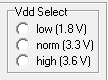
SelVddHigh=D0+D1+!D2+!D3
which will set both D0+D1 high and D2+D3 low when the supply voltage shall
generator shall be configured for "high supply voltage (see notes on simple
production-grade programmers).
If you have the source code of WinPic, look for "PicHw_TokenToInOutFunc()" to find out which tokens are implemented so far ;-)
To continue the installation of a customized programming interface...
If everything is ok, check the proper function of the control lines with the interface test option. Keep your interface definition file in WinPic's directory, because this file will be loaded whenever you start the program again (the definitions are NOT copied into the SETTINGS.INI file. Only the name of your interface definition file is saved in the settings !)
Since 2008, it is possible to add support for other interfaces in the form of a plugin-DLL. To use such a DLL, it must be copied into the folder "interface_dlls" (in the WinPic installation archive). Then, set the interface type to "Custom, on any port, from plugin-DLL" on WinPic's INTERFACE tab. Next, click the "Select"-button on that page. A file selector dialog will open up, asking you for the name of the interface-DLL in the folder mentioned above.
If you have developed your own PIC programming interface -possibly with a USB interface- and want to add support for it using WinPic, you can write your own interface DLL with a free C compiler like DevC++ V 4.9.9.2 . You will find the complete sourcecode for such a DLL on the author's website, along with the necessary documentation.
The "interface_dlls" folder will be empty after installation by default (except for a small readme file) to avoid bloating the WinPic installation archive. But a list of DLL-plugins for other PIC-programmers will be available on the WinPic website, as soon as such DLLs exist ;-)
Microchip's PIC requirements for a "production grade" programmer specifications require to verify the PIC at different voltages. If you think you really need this, you can use WinPic to drive a simple programming adapter which does this (it's a bit crude, however, see below).
The basic principle is this: WinPic controls the supply voltages with a few digital output lines of the parallel port. Your hardware can use this to switch a couple of trimpots which adjust the supply voltage. I have never built such a programmer myself (because I never missed such a thing) but if you'd like to, look into the file SimpleProductionGradeProgrammer.ini (it's in the zipped archive where you found WinPic.exe). Here is an example for the interface definition file of a "simple" production-grade programmer:
[ProgrammerControlLines]

DataIn=!ack

OkButton=!sld

VppOnOff=!D4

VddOnOff=D0

SelVddLow=D5+!D6+!D7

SelVddNorm=!D5+D6+!D7

SelVddHigh=!D5+!D6+D7

Connect=nc

ClockOut=D3

DataOut=D2
The definitions of the three "SelVdd"-macros control the supply voltage (here: D5 and D6 of the parallel port). WinPic executes the "SelVpp"- macros BEFORE switching on the supply voltage, with a pause of at least 100 milliseconds (enough to charge/discharge a capacitor with a few uF's). After settling of the supply voltage, it is actually turned on with the "VddOnOff" macro (here: D0 will be SET to turn the PIC's supply voltage on). Some PICs require a fast rise time of the supply voltage, so use a switching transistor controlled by the "VppOnOff" macro (D4 in this example), and place the buffering capacitor "BEFORE" the Vpp switch !
Suggestion: Use the "Vdd selection" lines to drive two or three NPN transistors, with trimpots in the collectors, and emitters connected to ground. The trimpots can be part of a voltage divider connected to an simple regulator. No need for an analogue switch !
To verify a PIC program at different voltages, you must turn on the option "Verify at different supply voltages" on the options tab. If the adapter does not support this (because the SelVdd-macro definitions are missing in the interface definition file, or are defined as "nc"=not connected), this option will be grayed and WinPic will ignore it (it will only do a single verification run then, instead of three runs with Vdd=Vdd_norm, Vdd=Vdd_min, Vdd=Vdd_max in this order). If one of the three possible voltage are not supported by the programmer, define the voltage control lines as "not connected" like this, which lets WinPic skip that verify-step:
SelVddHigh=nc
Note: This three-voltage-verification is not very smart. It takes about three times longer than verifying at a single voltage, and IMHO is not required for hobbyist purposes - and that's what we are talking about. It may be an issue if you plan to run a PIC very close (or even below) its specified operating voltage. In this case, it makes sense to verify it at that low voltage.
Adapter for PIC16F87x (28 pin SDIP)
This adapter was used to program a PIC16F876A with 28-pin standard DIP, using a programmer which was originally built for the 16F84/16F628 :
| Pin Function | Pin Nr & Name PIC16F628 (SDIP 18) |
Pin Nr & Name PIC16F876 (SDIP 28) |
Remarks |
| Power supply |
14 |
20 |
+ 5 V |
| Ground |
5 |
8 and 19 |
connect all |
| Prog Voltage |
4 |
1 |
12 V pulse |
| CLOCK |
12 |
27 |
|
| DATA |
13 |
28 |
|
Note: The 16F8xx may be affected by capacitive coupling from PGD to PCD (data to clock), so in case of trouble add two capacitors as described here.
The PIC12F629 / PIC12F675 is a low-cost PIC with 8 pins and flash memory, the F675 has four 10-bit A/D converters.
If you already made a (non-ICSP-) programmer for the once-famous 16F84 or 16F628 family, you need an adapter socket from 18-pin (16F84,16F628) to 8-pin (12F629/675). The pinout for the 12F629/675 is:
 (pinout PIC16F675)
 (my
ugly adapter)
(my
ugly adapter)
The following table helps to make an adapter from 18-pin PICs to 8-pin PICs:
| Pin Function | Pin Nr & Name PIC16F628 (18 pins) |
Pin Nr & Name PIC12F675 (8 pins) |
Pin Nr on SM6LKM's PIC FLASH board V1 |
Remarks |
| Power supply |
14 |
1 |
2 |
+ 5 V |
| Ground |
5 |
8 |
3 |
don't say |
| Prog Voltage |
4 |
4 |
1 |
12 V pulse |
| CLOCK |
12 |
6 |
5 |
|
| DATA |
13 |
7 |
4 |
|
Note: Though it looks ugly, this adapter may be (or may be not) used to program some 14- or 20-pin chips, too. For example, the ICSP pins of the PIC16F690 are at the same physical pins as for the PIC12F675, even though the pin numbers are not the same. But beware, some PICs have a "low voltage programming input" which needs to be tied to low level while programming.
Adapter for PIC10F20x (6-pin SOT-23 or 8-pin PDIP)
To program a PIC10F20x with your old "simple" programmer, you need yet another adapter, because the PIC10F20x 8-pin packages are not pin-compatible with the PIC12F6xx shown in the previous chapter ! (remember this before the smoke comes out). The following table may help to build an adaptor for PIC10F200/202/204 /206 :
| Pin Function | Pin Nr & Name PIC16F628 (SDIP 18) |
Pin Nr & Name PIC10F20x (PDIP 8) |
Pin Nr & Name PIC10F20x (SOT-23, 6 pin) |
| Power supply |
14 |
2 |
5 |
| Ground |
5 |
7 |
2 |
| Prog Voltage |
4 |
8 |
6 |
| CLOCK |
12 |
4 |
3 |
| DATA |
13 |
5 |
1 |
Handling of OSCCAL and Backup OSCCAL Value (by WinPic, for PIC10F20x)
The PIC10F20x only runs with an internal 4-MHz-RC-oscillator which must be
"calibrated" by moving a certain value into the OSCCAL registers in the very
first instruction of your application. The calibration value is the operand
of a MOVLW instruction at code memory address 0x0FF (or 0x1FF, depending
on the code memory size). There is a "backup" OSCCAL value (at address 0x104
or 0x204). WinPic reads both these locations before erasing the chip, and
restore them automatically if the read values are valid. If both calib values
in the PIC10F20x are invalid, WinPic will use the values from its code- and
config memory buffers. If the buffered values are also invalid (because they
don't contain a MOVLW opcode), WinPic will refuse to program the chip (unless
the option "Don't care for OSCCAL value" is set.
So, if you get the following error message ...
PIC10F: Abort programming (nothing erased). No valid OSCCAL value found !
Enter a valid BACKUP OSCCAL VALUE (like 0x0CF4) on the Config Register Tab, then try again !
... then switch to WinPic's "Config Memory" tab, where you can enter the OSCCAL value of your chip. Then hit "apply changes" and try programming again. To avoid losing the individual OSCCAL value of your precious sample, read it out and scratch the hexadecimal number into the PIC's plastic package - so you can always find it when you need it ... ;-)
This adapter was used to program a PIC16F684 with 14-pin SDIP case, using
a programmer which was originally built for the 16F84/16F628. I tested it
with a JDM-style interface and it worked ok. For details, consult Microchip's
specification DS41204 . The same socket was used for
PIC16F631/677/685/687/689/690 (20-pin DIP package), because the pins used
for serial programming are at the same physical locations though their pin
numbers are different.
| Pin Function | Pin Nr & Name PIC16F628, etc (18 pins) |
Pin Nr & Name |
Pin Nr & Name |
Pin Nr on SM6LKM's PIC FLASH board V1 |
Remarks |
| Power supply |
14 |
1 |
1 |
2 |
+ 5 V |
| Ground |
5 |
14 |
20 |
3 |
|
| Prog Voltage |
4 |
4 |
4 |
1 |
12 V pulse |
| CLOCK |
12 |
12 |
18 |
5 |
|
| DATA |
13 |
13 |
19 |
4 |
|
Note: If you already built the adapter for the PIC12F675 (with 8 pins), you
can program the PIC16F684 (with 14 pins) with it, too. Pin 1 of the PIC plugs
to pin1 of the socket. Pin 14 of the PIC16F684 plugs into pin 8 of the PIC12F675
adapter. Looks ugly but works .
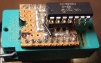
This adapter was used to program a PIC18F2550 with 28-pin SDIP case, using a programmer which was originally built for the 16F84/16F628. Though these chips have a USB interface, you cannot program them through USB (without extra hardware or a special bootloader).
Beware: The pinout of these PIC18F2x5x devices looks similar to other 28-pin
PIC16F devices and dsPIC's on first sight, but they are not pin-compatible
! The following table helps to build an adapter for PIC18F2455 and
PIC18F2550 devices, to be programmed with an old 18-pin PIC programming
interface. I tested it with a JDM-style interface and it worked ok.
| Pin Function | Pin Nr & Name PIC16F628 (SDIP 18) |
Pin Nr & Name PIC18F2550 (SDIP 28) |
Remarks |
| Power supply |
14 |
20 |
|
| Ground |
5 |
8, 19 |
connect all "ground" pins ! |
| Prog Voltage |
4 |
1 |
12 V pulse |
| CLOCK |
12 |
27 |
connect 22 .. 47 pF cap |
| DATA |
13 |
28 |
connect 22 .. 47 pF cap |
| LowVoltage Prog.mode |
- |
26 |
pull to GROUND to avoid |
Note: You don't necessarily have to connect RB5/KBI1/PGM to ground. But doing so makes sure the chip doesn't enter low-voltage programming by accident, because WinPic only uses standard ("high-voltage") programming at the moment.
Beware: The dsPIC30F2010's pinout looks similar to other PIC16F and PIC18F
devices on first sight, but it is not compatible ! The following
table may help to build an adapter for most dsPIC's with 28 pin standard
DIP case, to be programmed with an old 18-pin PIC programming interface:
| Pin Function | Pin Nr & Name PIC16F628 (SDIP 18) |
Pin Nr & Name dsPIC30F2010 (SDIP 28) |
Remarks |
| Power supply |
14 |
13, 20, 28 |
connect +5V to all supply |
| Ground |
5 |
8, 19, 27 |
connect all "ground" pins, |
| Prog Voltage |
4 |
1 |
12 V pulse |
| CLOCK |
12 |
18 |
connect 22 .. 47 pF cap |
| DATA |
13 |
17 |
connect 22 .. 47 pF cap |
(*) About PGD and PGC filtering: There
was a note on the Microchip forum (by Olin Lathrop) about programming the
dsPIC30F201x(**), suggesting to put 22..47 pF on the PGD and PGC lines to
ground near the target chip. In addition, put a 100 ohm resistor in series
with the PGD line between target chip and the cap. The resistor and cap on
the PGD line low pass filter the PGD signal when it is driven by the target
chip. This reduces the high frequencies that can couple onto the PGC line.
The cap on the PGC line makes it less suceptible to coupled noise.
(**) We later found out that this important note also applies to the
PIC18Fxxxx family. A user of a Velleman PIC programmer reported success with
a PIC18F4520 after adding 2 * 33 pF caps and a 100 Ohm series resistor.
The PGD / PGC filtering components are shown in the circuit diagram of
DL4YHF's modified programmer for the serial port.
If you don't find the PIC you want to program in the combo list on the tab sheet "Device,Config", you should try this:
If you still have no success after this, try to READ or VERIFY an already programmed PIC. Maybe the ICSP commands (In-Circuit Serial Programming) are totally different, or your PIC cannot be programmed or read via ICSP at all - bad luck ! The maximum code memory size is 64k WORDs.
At the moment, most FLASH-based PICs with 14-bit code words, and a few 12-, 16-, and 24-bit devices have been tested. If your copy of WinPic is older than a few months, look for an update on the author's ham radio/ homebrew homepage.
This file can be modified to make WinPic support a new PIC device. To add support for a new device which is not directly supported by WinPic,
The format of the file DEVICES.INI is explained in a separate document, along with the description of the parameters which must be added new PIC devices. Note: WinPic once loaded this file through a Windows API routine, but I changed this after the file grew too large, because Win98 can only read INI-files up to 64 kByte (why??) - so now DEVICES.INI is parsed line-by-line as a textfile.
Device definitions in DEVICES.INI will override the built-in definition table. So, if you find there is a bug in a device definition, add it into DEVICES.INI to let WinPic ignore its internal PIC device table. A message will be displayed in the status line and in WinPic's "Message" list.
Just a few links, not frequently updated. Some of them may already be "dead"...
Disclaimer: The links presented here are under the sole control, copyright
and responsibility of the authors of their pages. I am unable to take any
responsibility for the content of web-sites that you reach through these
hyperlinks.
This note has been added because of a court decision where the author of
a website was made responsible for the contents of "foreign" websites which
could be reached via a link from his own page !!!
--... ...-- ...-.-