Contents
See also: SpecLab's main index
The Colour Direction Finder in Spectrum Lab is based on a DOS QuickBasic-program written by Markus Vester, DF6NM. He made an excellent paper about the principle and some applications of his program (which btw is more versatile than the Colour Direction Finder implementation in SpecLab). Studying Markus' document is highly recommended ! In Summer 2003 it was available on this website:
http://members.aol.com/df6nm2/ColourDF/ColourDF.htm
If you have problems to find the file, search the net for :
Wideband Direction-Finder with Colour Encoded Spectrogram Display
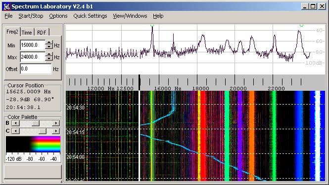
As the title suggests, it is a special kind of Spectrogram ("waterfall") which shows not only the intensity of a signal, but also the azimuth angle, sometimes even the elevation. The azimuth ("compass direction") defines the colour tone, the intensity (total field strength) affects the luminosity, and the elevation sets the colour saturation - if your reception hardware is capable of detecting the elevation of a signal. A screenshot of the upper part of the VLF spectrum, taken in RDF mode, may look like this:
The main purpose is Radio Direction Finding, with these possible antenna setups:
For acoustical direction finding, three microphones can be used in a similar combination.
From the program's point of view, there are just two different input configurations (at the time of this writing..). In the configuration dialog, they are called
The first of these combinations refer to a typical "longwave" radio direction finder as described by DF6NM, but you can use it for any system which uses one antenna pair with a 90° combiner (which produces a circular polarized signal, for example H_cp = Hx + j * Hy for a magnetic loop pair ), connected to the first input of the spectrum analyzer, and a single antenna for the other wave component (for example an E-field antenna, receiving Ez).
The antenna configuration "Two loops on separate inputs" is any combination of two crossed antennas with no external 90° combiner. For example, an East/West loop may be connected to the 1st input of the spectrum analyzer, while the North/South loop is connected to the 2nd input. (Usually you will connect the two inputs of the spectrum analyzer to the Left+Right input of the soundcard, but as you can see in the circuit window, you can connect them to other sources also).
Instead of two "magnetic" loops (H-field antennas), other antennas can be used in this configuration. Examples:
The signals from two orthogonal antennas are fed into the left and right audio input of the soundcard. A special software calculates spectra ("FFT"s) from the nort/south and east/west antenna, which contain phases and amplitudes for a large number of different frequencies. The amplitude ratio and phase between the two inputs can be used to calculate the angle of arrival.
Ideally the phase between the two inputs is either 0° or 180°, but nothing else. The bearing (azimuth) is calculated only from the voltage ratios and the "polarity" (0° / 180°). For example, there may be a fictional transmitter inducing up to 1 mV in main direction of any antenna. Let the fictional transmitter move around the observer's location ... the antenna voltages will be:
Transmitter bearing |
N/S voltage | E/W voltage | Phase difference |
0° (N) |
1 | 0 | not detectable / doesn't matter |
45° (NE) |
0.707 | 0.707 | 0° |
90° (E) |
0 | 1 | not detectable / doesn't matter |
135° (SE) |
0.707 | 0.707 | 180° |
180° (S) |
1 | 0 | not detectable / doesn't matter |
225° (SW) |
0.707 | 0.707 | 180° |
270° (W) |
0 | 1 | not detectable / doesn't matter |
315° (NW) |
0.707 | 0.707 | 0° |
Looking at this table, there is obviously a 180° ambiguity for the simple "two-antenna" configuration. Why ?
Because the program can only see the phase difference (here: ideally 0° or 180°) between the two antennas, but it can not see the absolute phase of the voltages induced in each antenna. For this reason, all possibly colour values appear two times on the 360° compass. (There is a solution for this ambiguity, but it requires a more complex antenna setup and is not the subject of this chapter).
As mentioned above, the software calculates amplitudes and directions not only for one single frequency, but for a large number of different frequencies. The results are displayed on the screen in a special kind of spectrogram, where the colour (hue) shows the direction and the intensity shows the signal strength.
If the phase between the loop signals is far away from 0 or 180°, the bearing calculation may become inaccurate. In this case, the program will reduce the colour saturation on the waterfall, unless you move the "Extra Saturation" slider into the rightmost position. The display may look "speckled" then.
For radio direction finding on VLF, a description of a compact loop with ferrite rods can be found here (DL4YHF site)
There is a special tab for the Colour Direction Finder on SpecLab's "Settings" dialog. You can open it from the main menu by selection "Options".."Radio Direction Finder".
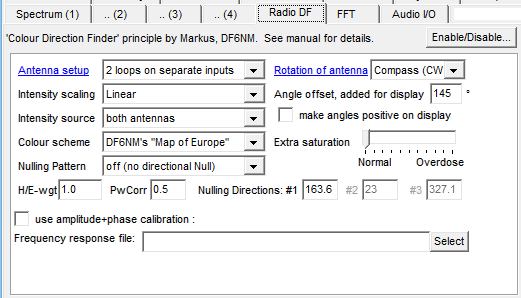
Intensity Scaling
Intensity Source
Colour Scheme
lets you select between DF6NM's original colour scheme which I called "Map
of Europe" and a user-defineable colour (hue) palette.
Extra Saturation
Nulling patterns (Nulling cardioids, with parameters H/E-weight, direction, power correction factor)
Unlike the normal waterfall, the Colour Direction Finder needs complex output
from the FFT routines. To activate the CDF, set the "FFT output type" to
"Complex output for RDF" on the FFT
control tab, or select one of the preconfigured settings for the radio
direction finder from the main menu (for example "VlfRdf1.usr",
which also produces an azimuth/amplitude plot over time for some submarine
transmitters).
Most of the standard settings like FFT resolution, decimation, sampling rate
etc also affect the Colour Direction Finder. In fact, the internal signal
flow is almost the same, only the last processing stages (after the FFT
calculation) are different between a normal spectrogram display and the Colour
Direction Finder. The important Contrast
/ Brightness controls for the waterfall also work in CDF mode, though
they only affect the luminance in this case.
Allows to correct the indicated bearings, if the readout is incorrect when the antenna is rotated (typically caused by swapped N/S and E/W antennas, or reversed polarity in one of the antenna connections).
 The display units for angles on the radio-direction finder is now
always CLOCKWISE (like on a compass). The counterclockwise 'math' system
isn't used for the display, because it made the implementation of the new
"multiple" nulling functions too complicated.
The display units for angles on the radio-direction finder is now
always CLOCKWISE (like on a compass). The counterclockwise 'math' system
isn't used for the display, because it made the implementation of the new
"multiple" nulling functions too complicated.
In the orthogonal loop antenna configuration, the 1st loop should be directed in EAST/west direction (~x), so signals from the east induce a "positive" voltage, the second loop should be directed in NORTH/south (~y).
See also: How to get correct compass bearings.
Some further fine adjustment can be done via sofware, for example if the antenna loops are not EAST/WEST and NORTH/SOUTH have to rotate your crossed-loop-antenna. Check the correct polarity of the antenna loops with a transmitter in a well-known direction, flip the Rotation of antenna parameter (if it seems to rotate the wrong way around), then modify the Angle Offset value until the indicated angle is correct (easier than reconnecting the antennas if there's no soldering iron at hand).
If there is a frequency dependent error in the azimuth value, or the antennas have different gains, use a calibration table as described in another chapter.
This function allows to suppress unwanted signals from one or more directions. Select one of the nulling pattern in the combo box :
The direction of the Null(s) must be entered in degrees on the colour direction finder control tab. Please keep in mind that the "Two Loops Only"-antenna configuration has a 180° angle ambiguity, so the nulling directions appear twice on the compass (a "single null" at 90° will automatically produce another null at 270° for example). To illustrate this, the nulling pattern is shown in the RDF-compass.
There may be other parameters for the nulling function which are not mentioned here yet (possibly a way to control the "sharpness" of the nulls in future).
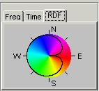
The RDF compass is displayed on the "RDF" tab of SL's main window. It shows a colour legend for the compass directions shown on the waterfall (in RDF mode, of course).
If the software nulling function is enabled, the nulling pattern is displayed too. The screenshot on the left shows the nulling cardioid. The display range is 40dB (0 dB = "no attenuation" at the colour disk's edge, 40 dB attenuation in the center of the circle). A small triangle at the perimeter of the compass disk shows the nulling angle(s); it can be moved with the mouse (grab the triangle with the left mouse button).
Note: Depending on the antenna setup, there may be a 180° azimuth ambiguity. This is reflected in the RDF compass too: All colours will then appear twice (once between 0° and 180°, and again between 180° and 360°).
See also:
For radio direction finding on ELF..VLF, you don't need a real receiver (with frequency conversion), you can connect the VLF antenna directly to the input of the A/D converter. For frequencies above 10..16 Hz, the soundcard is ok. For frequencies below 16 Hz, you'd be better off with an external A/D converter with DC coupling. A simple, compact VLF ferrite antenna can be found here (DL4YHF site).
For applications other than ELF..VLF, a two channel receiver is required with coupled local oscillators and BFO's. For LF, a single conversion superhet with an "IF" in the upper audio range may be sufficient, if the receiver has a narrow-band frontend. In this case, a hardware-IF stage and BFO can be replaced by software (select an IF of 10..20kHz, and let the soundcard run at 44.1 or 48 kHz).
Beware: Only use ONE local oscillator, and only ONE beat frequency oscillator for both receiver branches ! Even if you have two identic shortwave radios tuned to the same frequency, it won't work.
Sometimes the IF amplifier in a two channel receiver introduces a different phase shift for both RX channels. This can be compensated by software to a certain degree. The program can load a phase- and amplitude calibration table from a textfile as described in another chapter.
Because even a carefully constructed dual-channel receiver will have slight differences in the frequency response (especially the phases), there is the possibility to "calibrate" the amplitude- and phase readings from a table. The amplitude- and phase calibration table is loaded from a textfile. It only needs to contain a few calibration points for the "frequencies of interest", the rest will be interpolated automatically.
The format of the calibration table can be seen in the sample file "vlf_loops.fre" (the extension "fre" is an abbreviation for "frequency response", the format is used in other programs also). There is one text line for every calibration point in the file, with five coloumns:
Some comment lines (beginning with a semicolon) can be inserted anywhere in the file, so you can place additional information in it.
If you cannot measure the phase response of both branches in your dual channel RDF receiver, leave the "phase response" values in the table zero, and try to measure only the phase differences between channel 1 and channel 2, which can be achieved with SpecLab itself (ToDo: explain how !).
Internally, the calibration table is converted into complex numbers and interpolated for all FFT bins (for example 32768 complex values for 32768 FFT bins). So, if your amplifier has a relatively flat amplitude- and phase response (over frequency), you only need a few values in the table. If the calibration table does not cover the full audio bandwidth, the program assumes an "ideal" receiver : Missing amplitude values are set to 1; missing phase values to 0 .
For the antenna configuration "Two loops on separate inputs", the precise phase response is not as important as for "E-field antenna + 2 combined loops", because in the first case the direction is (mainly) calculated from the amplitude ratio, but not from the phase between the two inputs.
The name of the calibration file can be entered on the "Settings" tab. The frequency response calibration can be turned on and off quickly with the checkmark "use amplitude- and phase calibration" which is also on the "Settings" tab.
These functions for the radio-direction finder may be called from the built-in interpreter :
You can use these functions to show some RDF calculation results in the
watch list / plotter window, etc.