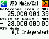
Both synthesizer output frequencies are independent. One doesn't "follow" the other.
- "Split: B = A + Shift"
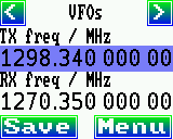
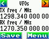
Intended for Amateur Radio use. Traditionally, transceiver often had
two 'VFOs' (A and B), and for 'Split' operation (common on shortwave),
the second VFO could follow the first with a fixed offset (the "Split" frequency).
Thus, in this mode, only VFO 'A' is freely tuneable, and the 2nd synthesizer
output produces VFO A's frequency PLUS the value entered in the
field titled 'Split or Shift / MHz'.
The 'Split or Shift' frequency field is typically set to the offset between
receive and transmit for FM repeaters (like 28.0 or -28.0 MHz for narrow-band
FM repeaters in Europe). More on FM-repeater-specific details in a later chapter.
1.1.4 Frequency Modulator / Waveform Generator
To test receivers, transmitters / PLLs / etc, or sweep RF filters,
the synthesizer has a built-in waveform generator for..
- sinewave
- sawtooth (when set to very low frequencies, usable as 'sweep' generator)
- rectangle (planned, but not implemented yet; least important..)
In addition, the first RF output can be frequency-modulated with
an analog signal ('audio', 'voice', or the demodulated output
from an FM receiver when used in an FM repeater) fed into one of
the dsPIC's analog inputs - more on
that in a later chapter.
The maximum frequency deviation and the modulating signal frequency
can be freely selected via rotary encoder on the 'Modulation' page:
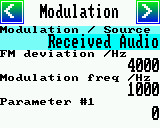
- FM deviation / Hz
- This is the maximum excursion of the frequency-modulated RF signal
to either side (below and above the 'center frequency').
For example, with the 'TX Frequency' set to 145.500 MHz,
and the 'FM deviation' set to 4000 Hz, the momentary RF frequency
will swing between 145.496 and 145.504 MHz.
Note: The resulting 'occupied FM bandwidth' will not be 8 kHz,
but more ! Carson's rule for FM bandwidth says that 98 % of the
RF signal power will be in
BT = 2 * ( deviation + modulating frequency ),
where
BT = total bandwidth (in Hertz) for 98 % power,
deviation (aka 'delta f') = value in the above field,
modulating frequency : value in the field below,
or (when not modulated with a sinewave but e.g. voice):
highest frequency contained in the audio signal.
- Modulation frequency / Hz
- Only has an effect if the 'Modulation Source' is set to
'Sinewave', 'Sweep/Sawtooth', or any future synthetic waveform
generated by the dsPIC firmware itself,
but not if the source is e.g. 'Received Audio' or 'Filtered Audio'.
- Parameter #1
- This is a 'freely useable' integer parameter, which may be used
as a constant (but editable) input for the frequency modulator.
The main purpose was for software testing, while developing
methods to frequency-modulate the Si5351A by rapidly
reprogramming the PLL feedback divider or 'Fractional Output Divider'
(aka 'Multisynth' in Si5351 datasheet parlance).
1.1.5 Display Setup
The 'Display Setup' can be invoked through the 'Menu' button on the main page (e.g.
'VFO' in the RF synthesizer, or similar page in other applications).
Items in the 'Display Setup' menu (there may be more than descibed here, in future versions):
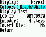
- 'Display:'
- Can be used to rotate the screen by 180° (in certain devices also by 90° and 270°
for two different 'portrait' modes).
For the RF synthesizer firmware (and most 1.8 inch display adapter boards),
'Normal' means landscape format with the display connector on the left;
'Upside down' means landscape format with the display connector on the right.
In other projects (using the same software driver modules for a different purpose),
there may be more options selectable for this parameter.
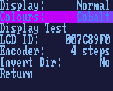
- 'Colours:'
- Select one of the built-in colour schemes.
There are bright schemes like 'Black/White' (black characters on white background),
warm-toned schemes (e.g. 'Cappucino'), darker schemes, etc.
Using a darker scheme (like 'Cobalt') is the only way to dim the display,
because there is no backlight control signal on most low-cost TFT panels.
- 'Display Test:' (optional)
- Used for troubleshooting, e.g. when adapting the LCD driver for new TFT panels.
See chapter 'Finding a suitable LC display'.
- 'LCD ID:' (followed by a hexadecimal value)
- Used for hardware debugging. The hexadecimal value is (usually) a 24-bit identifier
read from the LCD driver chip. If the hex value is 007C89F0, the connected
display is equipped with a ST7735 driver.
- 'Encoder:'
- Select the type of rotary encoder here. So far, possible settings are
one, two, or four Gray Code steps per detent ("notch"). For details,
see the functional description in a later chapter.
- 'Invert Dir:'
- If, when turning the encoder, the navigation bar moves into the wrong direction,
change this setting from 'No' (encoder direction not inverted) to 'Yes' (inverted)
or vice versa.
1.2 Remote control / Command interface
To keep the firmware simple, the 'command interface' for the UART
uses half-duplex mode, just a single wire, and a single I/O pin on the dsPIC.
Commands can be sent from the PC using an ordinary terminal program like 'TeraTerm',
and a simple passive interface between the dsPIC's I/O pin (internally
remapped to both the UART's TXD-output and the RXD-input, thus the need
for half-duplex operation). Command lines must be delimited by carriage return
and/or new line character ('\n' or '\r' for those familiar with "C").
With a few exceptions, the dsPIC firmware will also respond with a line of text,
or multiple lines of text. In the examples listed futher below,
<enter> simply means 'press the ENTER key at this point'.
At the time of this writing, the following 'commands' were supported:
- h<enter> : Show help. At the moment, this only prints a short
message pointing you to the URL with the documentation. Since you are
just reading the documentation, you certainly won't need the 'help'
command, or already found it by trial-and-error.
- s<enter> : Send a screenshot of the synthesizer's graphic display.
After sending this command, convince your favourite terminal program
to store anything it receives from the serial port in a binary file.
Example in Tera Term:
"File".."Log".. Filename: screen1.bmp,
Option: [v] Binary (check!) [ ] Append (uncheck!).
It's important that the terminal doesn't replace any received character (byte)
by some other character, because otherwise, the recorded file will not
be a valid windows bitmap file.
There's a catch due to the HALF DUPLEX operation: Because RXD and TXD
are connected together, anything you send from the terminal
will be echoed back (from the RS-232 port's TXD directly to RXD),
and after starting the file recording, be stored in the file's first byte.
For this reason, after receiving the 's' command, the PIC firmware will
wait for you (to start recording to a file) and send a single letter
'B', not followed by pressing ENTER.
Because the terminal program isn't aware of the 'echo' from TXD to RXD,
it will store the 'B' character in the first byte of the logged file.
For screenshots sent in the form of a Windows 'BMP' file, the first TWO
bytes always contain 'BM'. Thus, after reconfiguring its serial port from
'Receive' to 'Transmit', the synthesizer simply omits the 'B', and starts
sending the bitmap file at the 'M'.
With 160 * 128 pixels, 16 bits per pixel, roughly 390 kbits per screen
(including some overhead for start- and stopbits), and 115.2 kBit/second,
sending a screenshot takes less than four seconds.
After that time, turn off the 'file logging' in four favourite terminal program
(in TeraTerm: "File".."Show Log Dialog"..
"Close", which closes THE FILE, not just THE DIALOG).
Taking screenshots this way is akward, but it can even be done
remotely (without the need for a digital camera pointing at the
screen), and in fact all screenshots you see in this documentation
were made that way.
To frequency-modulate the RF output with audio signals (or even to
generate narrow-band FM for ham radio transmitters), one of the
dsPIC's analog inputs is used to digitize the audio signal.
The ADC input voltage range is 0 to 3.3 Volts (directly at the dsPIC),
so an audio signal must be properly biased with a DC offset
of approximately 1.6 Volts (half analog supply voltage),
and amplified to a peak-to-peak voltage not exceeding
3.3 Volts.
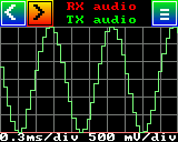
Use the built-in 'oscilloscope' to check the bias ('flat line'
centered, proper audio levels, "not too weak and not too strong").
The analog input, digitized with ~50 kSamples/second, runs through
some digital signal processing, and (after at least some low-pass
filtering) is finally sent to the Si5351 about 15..16000 times
per second (more about this bottleneck in a future chapter
about the principle of frequency-modulating the Si5351A -
not the Si5351B, which is trivial to 'modulate', but unavailable).
2. Functional description
ToDo: Add this chapter...
2.1 Principle
ToDo: Add this chapter...
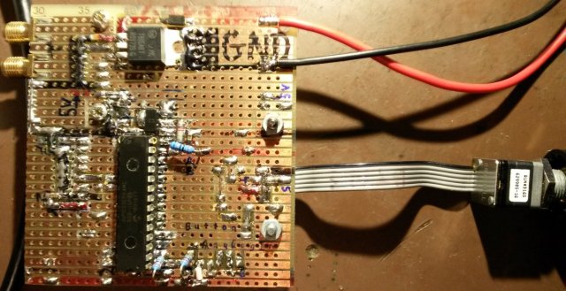
2.2 Homebrew prototype board (with dsPIC33EP512MC502-I/SP)
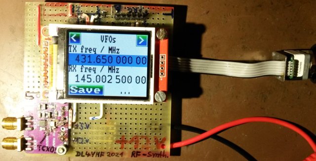
Si5351 Synthesizer Prototype by DL4YHF, top side with LCD.
For the prototypes, a synthesizer board designed by Adafruit, already
populated with an Si5351 was used. It can be seen in the lower left
corner in the image above. The violet coloured boards are not original
ones, but Chinese clones (which to my regret was noticed too late).
Compared with the original board by Adafruit, the oscillator populated
on the clone drifted quite a lot by temperature, so the cheap 25 MHz
oscillator was replaced by TCXO type 'TG2520SMN 25.000M'. This turned
out to be an excellent and very affordable choice (less than 2 Euros
at Mouser; no 'steps' as observed with other
digitally controlled TCXOs, and stable enough even without GPS
synchronisation, when generating narrow band signals in the GHz range.)
Mounting the tiny SMD TCXO 'dead-bug style' in place of the stock
oscillator was a challenge but worth the effort.
Si5351 Synthesizer Prototype by DL4YHF, bottom side,
with the dsPIC33EP512MC502-I/SP (very homebrew-friendy).
The block diagram, with all the dsPIC pin functions,
is shown in the appendix.
3. FM Repeater Setup
This chapter is intended only for sysops of Ham Radio FM Repeaters,
in experimental setups using the frequency modulated synthesizer
output to drive a VHF- or UHF transmitter.
Neither the dsPIC nor the Si5351 can receive RF signals
or even demodulate them, but the Si5351's second RF output can be
configured to 'follow' the transmit frequency with a freely adjustable
offset. So the Si5351 can replace the 'local oscillator' for the
VHF / UHF receiver's first mixer. Similar as for the first RF output,
the Si5351's 2nd RF output can be configured to generate just a
fraction of the final RF frequency, as typically used
in 'frequency multiplying' configurations (more on that later).
Since the Si5351's output phase noise increases on higher 'harmonics',
don't use a 'filtered harmonic' near e.g. 439 or 1298 MHz to drive a transmitter directly.
Instead, let the Si5351 generate a low output frequency (frequency-modulated
with a fraction of the FM deviation on the final transmit frequency), and either
a PLL with a narrow loop bandwidth (to remove any spurs), or an narrow-band
L/C filter between the squarewave output of the Si5351 and the PLL or classic
multiplier chain.
For example, the synthesizer may may drive a frequency multiplier chain
(or a PLL-based frequency multiply with a fixed divide-by-2^N feedback)
for a frequency-modulated UHF transmitter in the 23 cm Amateur Radio band:
   _________________              ___________    _______________
  |   Synthesizer   | 20.28 MHz  | Filter    |  | F.-Multiplier | 1298 MHz
  | "VFO": 1298 MHz |----------->| 20.28 MHz |->|    (*64)      |--------> ...
  |_________________| +/-62.5 Hz |___________|  |_______________| +/- 4 kHz
In this example, the 'TX freq multiplier' would be set to 64.00.
The dsPIC firmware is aware of the external frequency multiplication,
and will..
- not emit 1298 MHz (it cannot.. the Si5351 allows up to 160 MHz)
but 1298 MHz / 64 = 20.28125 MHz;
- make the FM deviation only one 64th as 'wide' as you entered,
here for example 4 kHz / 64 = 62.5 Hz
(Reason: The multiplier chain, or PLL-based frequency multiplier,
will not only multiply the carrier frequency but also the
FM deviation by the same factor, in this example 64 times)
The input to the external frequency multiplier (or PLL with div-by-64 feedback)
would be something near
1298 MHz / 64 = 20.28 MHz.
When measured with a spectrum analyser, the strongest unwanted spurs
in the Si5351's output near 20.28 MHz were about 57 dB below the wanted
'carrier':
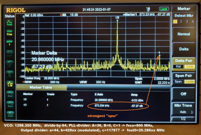
Output spectrum of a frequency-modulated signal from an Si5351A(!) near 20.28 MHz.
The origin of the strongest 'spur' 573 kHz below and above the 'carrier'
has not been discovered yet. It may have been a switching-mode regulator.
To be continued ...
still waiting for a divide-by-64 IC capable of a few GHz input to arrive,
to build a 'clean' UHF sinewave generator for a proof of concept.
4. Appendix
4.1 Firmware
The firmware for the dsPIC was originally developed for a dsPIC33EP64MC502
(available in homebrew-friendly DIL-28 housing, order it with
"-I/SP" after the device name).
Later, when running out of Flash and RAM, a pin compatible dsPIC33EP512MC502
(with 512 kByte Flash + 48 kByte RAM) was used instead.
Download the compiled firmware for the Si5351 synthesizer / experimental FM repeater control / Frequency Modulator (*.hex file[s])
Since a few prototypes populated with a dsPIC33EP64MC502 still exist,
the zipped firmware archive linked above also contains a firmware compiled
for the 'small' chip. If you plan to build your own, use the
dsPIC33EP512MC502 because sooner or later new functions will only
be available for the dsPIC33EP512MC502 (maybe including a custom bootloader
that eliminates the need to use a PICkit for a firmware update);
but unfortunely, and in contrast to modern CPUs like ARM/Cortex,
these chips don't seem to be shipped with an already programmed
bootloader. So, since I neither sell kits nor do I run a dsPIC
programming service, you will need to 'Flash' the firmware into
the dsPIC yourself - at least once.
For the brave-hearted, the zipped firmware archive contains a very
preliminary 'How-to compile or download the firmware' into the dsPIC.
If you already have a PICkit 3 or 4, or a 'Curiosity' development
board with a built-in PICkit ("PICkit-On-Board"), you already have
everything you need to download the firmware yourself.
There's a "standalone" utility named
IPE
(Integrated Programming Environment) available at Microchip
which should make this a bit easier than trying to 'flash'
an imported hex file with MPLAB X.
4.2 Sourcecode
A lot of effort has been put into the development
of the firmware, and to find the best method to frequency-modulate a standard
Si5351A. To avoid 'theft of intellectual propery' by you-known-whom
(as happend more than once to other of the author's projects),
only the sourcecode driving the Si5351 is available, but not the entire GUI
(which is less interesting anyway, since it was designed to run on a dsPIC
with low memory footprint).
If you're just curious about how to frequency modulate
an Si5351 with an audio signal (sufficiently clean for narrow-band
audio transmission as commonly used in Amateur Radio), the heart
of the firmware (si5351.c) is available here (si5351_c_source.zip).
4.3 Block- and Circuit diagram
There's no nice circuit diagram yet, since due to a lack of time,
the author's transition from Eagle to KiCad hasn't taken place yet,
and new projects will definitely not use Eagle anymore.
For the moment, there is just this snippet from the main module's
C sourcecode (!) with an ASCII-drawing of the most vital parts:
// CPU Connections / circuit principle
//
//                 ||                GND
//  +3.3V O--*-----||------*----------*----,           Analog input for audio/
//           |     ||     _|_         |    |            frequency modulator, etc.
//           |                        |    |         Analog input.. |
// I2C-bus   | Rotary Encoder         |    |      Encoder-    for   |
//   to      |  Ph.A  Ph.B            | ..(3)...... button    RSSI/ |  PICKIT
// Si5351:   |   ___  ___             | :Debugger : ___       discr |   (1) (Mclr/
// SCL SDA   |    |    |              | : and ICSP:  |         |    |    |   debug)
//  |   |    |    O    O              | :(PICKIT) :  O    ?    |    |   .-.
// /|\ /|\   |  \    \                | :.(4)..(5):   /   |    |    |   | |100
//  |   |    |   \    \               |    |    |    /    |    |    |   |_|Ohm
//  |   |    |    O    O    |XTAL|    |   \|/  \|/   O    |    |    |    |
//  |   |    |    |    |   /|\  \|/   |   /|\   |    |    |   \|/  \|/   *----,
// ,'   |    |    |    |    |    |    |    |    |    |    |    |    |    |    |
// |    _    _    _    _    _    _    _    _    _    _    _    _    _    _    |
// |   | |  | |  | |  | |  | |  | |  | |  | |  | |  | |  | |  | |  | |  | |   |
// | ,----------------------------------------------------------------------, |
// | | 14   13   12   11    10   9    8    7    6    5    4    3    2    1  | |
// | | RB5/ Vdd  RA4/ RB4/ RA3/ RA2/ GND  RB3/ RB2/ RB1/ RB0/ RA1/ RA0 MCLR*| |
// | | RP37/     RP20 RP36  OSC2 OSC1   PGED1 PGEC1 AN3/ AN2/ AN1 /AN0  __  | |
// | |I2C:SDA                                      RPI33 RPI32         /  \ | |
// | |                  dsPIC33EP512MC502-I/SP (SPDIP-28)              \__/ | |
// | |I2C: SPI1 SPI1  SPI1          RP42/ RP43/ RPI../  RPI46/ RPI47/       | |
// | |SCL/ CLK/ MOSI/ MISO/         PWM3H/..L PWM2H/..L PWM1H/ PWM1L/       | |
// | | RB6  RB7  RB8  RB9  GND Vcap  RB10 RB11 RB12 RB13 RB14 RB15 AGND AVdd| |
// | | 15   16   17   18   19   20   21   22   23   24   25   26   27   28  | |
// | '----------------------------------------------------------------------' |
// |   |_|  |_|  |_|  |_|  |_|  |_|  |_|  |_|  |_|  |_|  |_|  |_|  |_|  |_|   |
// |                        |    |                                  |    |    |
// |    |    |    |    |    |   _|_   |    |    |    |    |    |    |    |    |
// |   \|/  \|/  \|/  \|/   |   ___  \|/  \|/  \|/  \|/  \|/  \|/   |    |   _|_
// '----'    |    |    |   _|_  _|_   |    |    |    |    |    |    *-||-*  |   |
//        ..(7)..(6)..(5).......      |    |    |    |    |    |   _|_   |  |1k |
//        : SCK  SDA  A0   /CS(3)-<-- | -- | ---'  Debug- |    |   GND   |  |___|
//        : 1.8" TFT Display   :      |    |        LED            +3.3V O    |
//        : with SPI interface :   Single- |        _|_            GND   |    |
//        :  VCC GND RESET LED : wire UART |       |   |           ,--------, |
//        :..(1).(2)..(4)..(8).:  (uart.c) |       |1k |           |MAX809T | |
//            |   |    |   _|_        Single-wire  |___|           |(3V    >|-*
//            |   |    |  |6.8|       CAN-bus (?)   _|_            | Reset  | |
// +3.3V o----*  _|_   |  |Ohm|     ("C1TX"+"C1RX"  \|/ ->         '--------' |
//            |  GND   :  |___|      on one pin?)   -+- -> (red)       |      |
//            |_____________|                       _|_               _|_     |
//                     :______/_______________________________________________|
//                            \ /LCD-Reset (*) from /CPU-Reset, MAX809
//
//   For the recommended DC 'decoupling' capacitors and the super-important
//   'CPU Logic Filter Capacitor' ("Vcap"), see DS70000657J pages 31 .. 32.
//
// (*) "LCD-RESET" doesn't need to be driven via GPIO. The display's ST7735
//     was happy with A SINGLE RESET after power on, as shown above from the
//     'Reset Generator' chip, MAX809T .
//
// ICSP and debug adapter pins ON PICkit3(!)
//      1 = MCLR/Vpp  2 = Vcc
//      3 = GND       4 = PGD/RXD
//      5 = PGC/TXD   6 = LVP (nc)
//   For IN-CIRCUIT PROGRAMMING (without debugging), the "remappable" UART pins
//   may be useable on RB3 and RB2. During normal runtime, they
//   could be used to exchange data with the PC over a serial port (RS232).
//
// Simplistic 'microphone preamp', also acts a protection for the
// PIC's analog input (because the preamp is powered by the PIC's Avdd,
// the analog input voltage will never exceed the analog supply voltage):
//
//                                      ca. 1.7 V DC at the collector
//                            ___      /           ___
// 500 mVpp in          R3 ,-|___|----*-------*---|___|-----O Avdd (+3.3V)
//                         |  100k    |       |   R4 3k3
//    C1 | |   R1 ___ 3k3  |         |/  C    |    ___  2.8 Vpp out + 1.7 V DC
//  O----| |-----|___|-----*---------|        '---|___|--*--O --> RA0/AN0
//       | |      ___      |      B  |\| E       R5 1k __|__ C2
//    470 nF ,---|___|-----'          -| BC547         _____ 10 nF
//          _|_   R2  56k             _|_ or similar    _|_
//
//     Lower cutoff frequency (from C1, R1) : ca 100 Hz
//     Upper cutoff frequency (from C2, R5) : ca 15 kHz
//   The dsPIC samples the input at f_sample = ca 50 kHz, so that's ok;
//   most of the lowpass-filtering will be performed by the DSP anyway.
//   The proper DC bias can easily be checked with the built-in "oscilloscope".
4.4 Finding a suitable LC Display (1.8" TFT with ST7735)
On the author's first prototype, a 'JD-T18003-T01' on a red adapter
board with SD memory card adapter, and an 8-pin display connector
was used. The following pinout only applies to this particular adapter board:
| Pin # | Function |
|---|
| 1 | Vcc (+3.3 Volt supply voltage) |
| 2 | Ground |
| 3 | /CS (Chip Select input) |
| 4 | /Reset (connect to low-active system reset) |
| 5 | Register/Data Select (input, aka "A0") |
| 6 | SDA (serial data, bi-directional, MISO and MOSI combined) |
| 7 | SCK (serial clock, input only) |
| 8 | Backlight (connect to Vcc via 6.8 Ohm) |
Any 1.8 inch TFT with an ST7735 'display driver' inside, and an SPI-like
serial interface, 3.3 Volt supply voltage, 3.3 Volt logic levels for digital
in- and outputs should be fine. Beware of the incompatible pin-outs of
many of those 'adapter boards' that often came along with an SD- or Micro-SD
memory card adapter on the same PCB (more about the SD memory card support
by the dsPIC firmware in a future chapter).
After running out of stock with older 1.8" TFT modules with ST7735 controller,
a couple of '1.8" Arduino Module SKU:MAR1801' were bought for a fair price.
They also have the ST7735 controller inside (for the 160*128 or 128*160 pixel
TFT display). But the author just didn't get the display running properly:
Any attempt to read the chip-ID or framebuffer failed, and all
screenshots (made via RS-232 for this documentation) were black.
The reason later turned out to be a stupid UNI-DIRECTIONAL driver
between LCD connector and the ST7735's BI-DIRECTIONAL serial data line
on the red adapter board shown on the fotos below.
Since the supply voltage and the logic levels are 3.3 Volts, the unidirectional
driver (an SN74LVC245A with 'DIR' and '/OE' tied to fixed levels) was removed
from the red interface board of the '1.8" Arduino Module SKU:MAR1801',
as shown in the two photos below (before and after the modification):
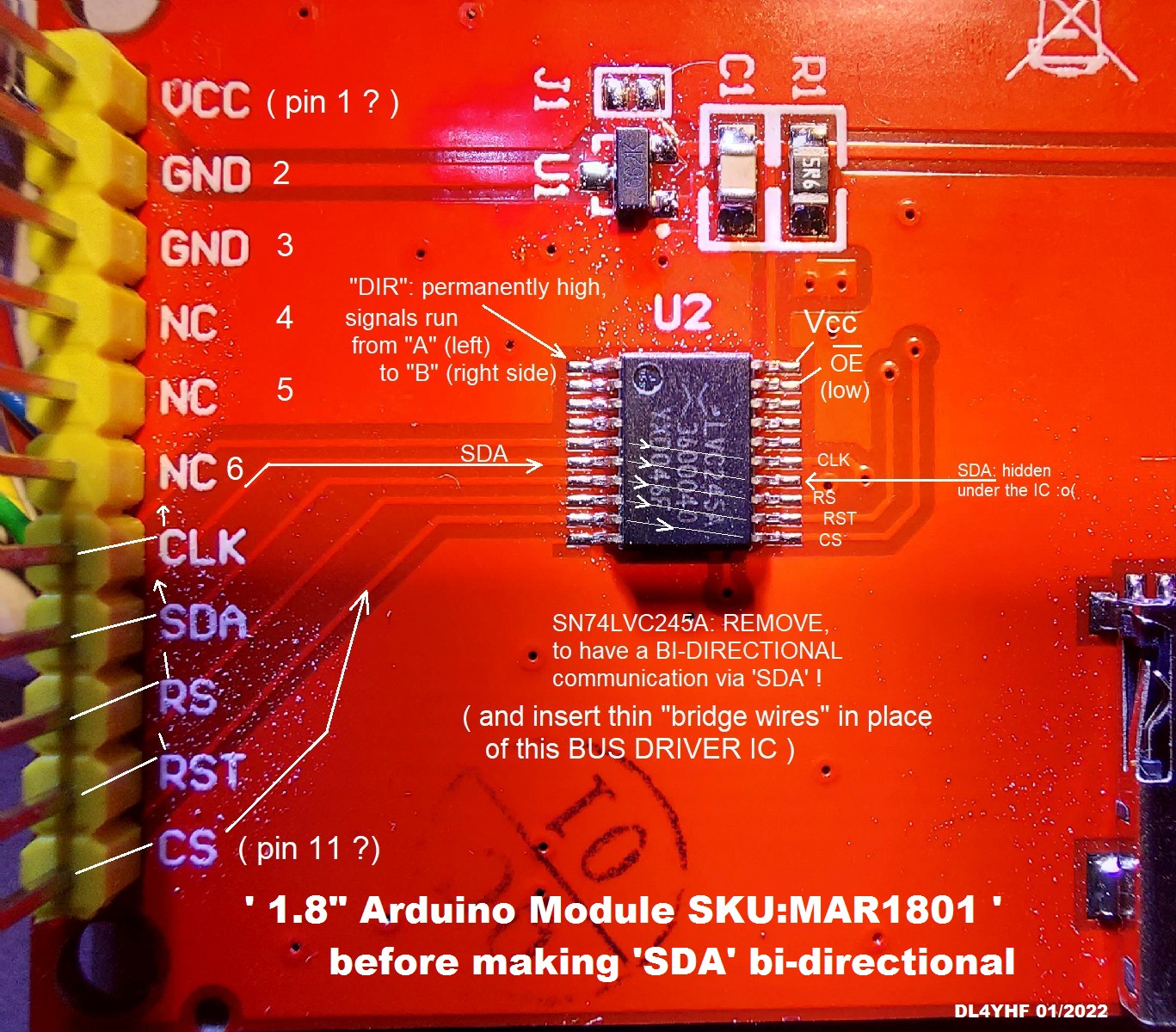
Mini TFT (bought as 1.8 inch "Arduino SKU:MAR1801") before modification.
Click on image to magnify.
Remove the bus driver (IC labelled 'LVC245A'), and replace the links with tiny wires
as shown in the photo below (or use a differnt display, or do without the
'remote screenshot' feature):
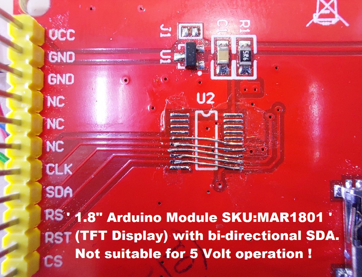
Mini TFT (1.8 inch "Arduino SKU:MAR1801") after modification.
Without the level shifter, this display cannot be driven with 5 Volts anymore !
Click on image to magnify.
The dsPIC's internal RAM is too small for a graphic framebuffer
(the originally used dsPIC33EP64MC502 has 8 kBytes of RAM; a framebuffer
with 160 * 128 pixels * 2 bytes per pixel would require 40 kB).
So to read back the framebuffer, the serial data line (SDA)
had to be made bi-directional (the firmware now runs
without a bi-directional SDA line, at the expense of the 'remote display' /
'screenshot-via-UART' feature presented in another chapter).
Both the dsPIC and the display are powered by 3.3 Volts in this
application, so no problem with the modification.
If the display is sufficiently compatible with the originally used
'JD-T18003-T01' (panel with integrated ST7735 controller, and SPI),
the colours displayed by the 'Display Test' (colour gradient fill
with white grid lines, and a one-pixel wide white border around the screen)
should look as follows:

'Display Test', can be opened through the menu via 'Display Test/Setup'.
If the colours are wrong, or the display image is offset by a few pixels
(vertically or horizontally), you've got one of those panels with an
'unusual' connection between the driver (ST7735) and the graphic
rows / coloumns for the pixels. Try another of those
low-cost TFTs. The Ebay/Banggood/Aliexpress/etc sellers often don't know
what they sell themselves, or the info given in their ads is plain wrong.
The price of these modules doesn't justify spending days(!) modifying
the driver software to get them running.
Again, a 128*160 pixel TFT with an ST7735 and a BI-DIRECTIONAL
SDA line should be fine. Be very cautious with the connector pinout,
and if the ad / website doesn't give you that information, don't buy.
4.5 Links (external)
Website by Hans Summers, G0UPL, with an Si5351A on a breakout board
Adafruit site with another Si5351A breakout board
(unfortunately, when last visited in 01/2022, "Out of Stock")
PIC Notes by DL4YHF
(with a lot of curses about a bulky IDE, and a long journey to get along with its bugs)
4.6 Disclaimer
The author provides this software "AS IS" without warranty of any kind, either expressed or implied,
including, but not limited to, the implied warranties of merchantability and fitness for a particular purpose.
The entire risk as to the quality and performance is with you. In no event unless required by applicable law
will the author and/or any other party who may modify and/or redistribute this software be liable to you for damages,
including any lost profits, lost monies, or other special, incidental or consequential damages
arising out of the use or inability to use this package, or for any claim by any other party.
This program is still "under construction", and there are certainly a number of bugs lurking in the code.
The entire risk is with you. You may find udates at the DL4YHF website (search for DL4YHF Si5351 Synthesizer) .