Modifications for Retevis RT3 / Tytera MD-380 (?)
by Wolfgang "Wolf" Büscher, DL4YHF
Last updated 2017-05-14 (Alternative menu, Morse output and software-controlled brightness). |
Main website:
www.qsl.net/dl4yhf
This page:
/RT3/index.html
|
RT3 modifications
Disclaimer
Proceed at your own risk ! The modifications on this page may not work with your radio, and the findings described here
may only apply to a single unit. The author won't be liable for anything at all, blah, blah.. (consider this as the usual disclaimer.
It also applies to the description of firmware modifications, and to any link you may find on this webpage).
 The Retevis RT3 is a monoband handheld transceiver for DMR (digital voice) and analog FM. It is almost identical to the Tytera MD-380.
You certainly already know the radio (since you visited this page), where to find the programming software, and how to prepare a suitable "codeplug" (configuration) to operate via repeaters in your area.
The Retevis RT3 is a monoband handheld transceiver for DMR (digital voice) and analog FM. It is almost identical to the Tytera MD-380.
You certainly already know the radio (since you visited this page), where to find the programming software, and how to prepare a suitable "codeplug" (configuration) to operate via repeaters in your area.
If you don't, ask the big brother for "Retevis RT3" or "Tytera MD-380". Don't miss ham-dmr.de,
the codeplugs by DK4WN, the descriptions by
DG9VH,
the introduction You and your MD-380 by AC2SN (known as ladyada),
the programming software at Retevis and VA3XPR,
and (for experienced users and developers) the 'Experimental' firmware by KK4VCZ.
Last not least, there is md380.org with a user-friendly
summary of the features of the MD380 tools,, main focus on the experimental firmware.
Contents
1. Hardware Modifications
2. Codeplugs
3. Software / Firmware Modifications
- Save the 'factory calibration' with the Retevis / Tytera CPS
- Upgrading Firmware with Retevis/Tytera 'Upgrade.exe' (under windows)
- Installing KK4VCZ's 'Experimental' firmware
- Building KK4VCZ's MD380 Tools on windows
- Downloading firmware with the MD380-tools
- Updating 'USERS.CSV' and downloading it
- More firmware experiments ..digging in deeper
- Morse output as an aid for visually impaired operators
- Alternative menu (project name 'red-key menu', short 'app-menu')
- Ad-hoc talkgroup entry (direct input of a temporary talkgroup number)
See also (related subjects on the author's website):
MD380 firmware overview
MD380 hardware details and measurements
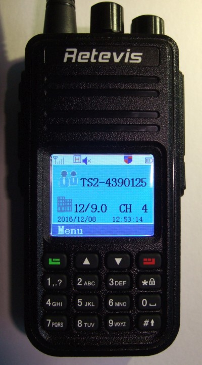
The RT3 was shipped with several accessories, including a charger for the radio's 7.4 V LiIon battery.
That charger has a bi-colour LED on the front side, which should indicate 'red' while charging, and 'green' when fully charged.
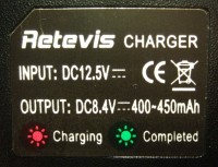 According to the label, charging current should be around 400 to 450 mA. Thus a 2000 mAh LiIon accumulator (2 cells in series as a "battery") should
have been charged within 5 hours. My expectation was the LED would switch from red to green after this time.
According to the label, charging current should be around 400 to 450 mA. Thus a 2000 mAh LiIon accumulator (2 cells in series as a "battery") should
have been charged within 5 hours. My expectation was the LED would switch from red to green after this time.
But it didn't. In fact, the LED never turned green. After removing the radio from the charger, and checking the voltage
directly at the battery terminals (see next chapter), almost 8.6 Volts were measured. Ooops ! That's a bit much for two LiIon cells in series !
In the interest of lifetime, the voltage for a single cell should never exceed 4.2 Volts. More voltage will not "fill in" significant extra charge,
but reduce the battery's life time. So the charger was modified as described below, to achieve a 'healthier' max output voltage of 8.4 V (for two cells in series).
The principle is easy. The charger shipped with the RT3 uses an MC34063
in a switching-mode step-down converter configuration.
This IC uses an internal reference voltage of 1.25 V, which is compared against the charger's output voltage ("8.4" V) divided down to 1.25 V.
The voltage divider consists of resistors R3A (33 kOhm) paralleled with R3B (1.8 kOhm), resulting in 1.707 kOhm, and R4 (10 kOhm) in series.
                                       ____
                      R4         ,----|____|----|
                      ____       |  R3A : 33 kOhm
      +"8.4" V  -----|____|------*
     (battery                    |     ____
      voltage)       10 kOhm     *----|____|----|
                                 |  R3B : 1.8 kOhm
                                \|/
                              1.25 V (to MC34063 control input, pin 5)
The regulator's theoretic output voltage with the original components (shown above) is
1.25 V * ( 1 + 10 kOhm / 1.707 kOhm ) = 8.57 V .
This 'surprisingly high' voltage for a 2-cell LiIon battery pack was confirmed by measuring it at the battery after removing it from the charger !
Almost 8.6 V is quite a lot for two LiIon cells in series, especially if the radio was kept in the charger for longer than necessary.
So how to reduce the charger's maximum output voltage ?
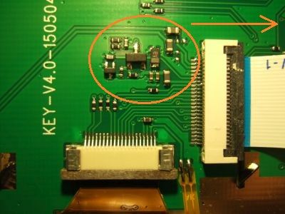
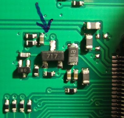
The photo below shows the charger's PCB, component side, with the originally populated resistors (R3A, R3B, R4 labelled in white),
and a few voltages measured when the battery was fully charged (but the LED was still 'RED' when it should have been 'GREEN').
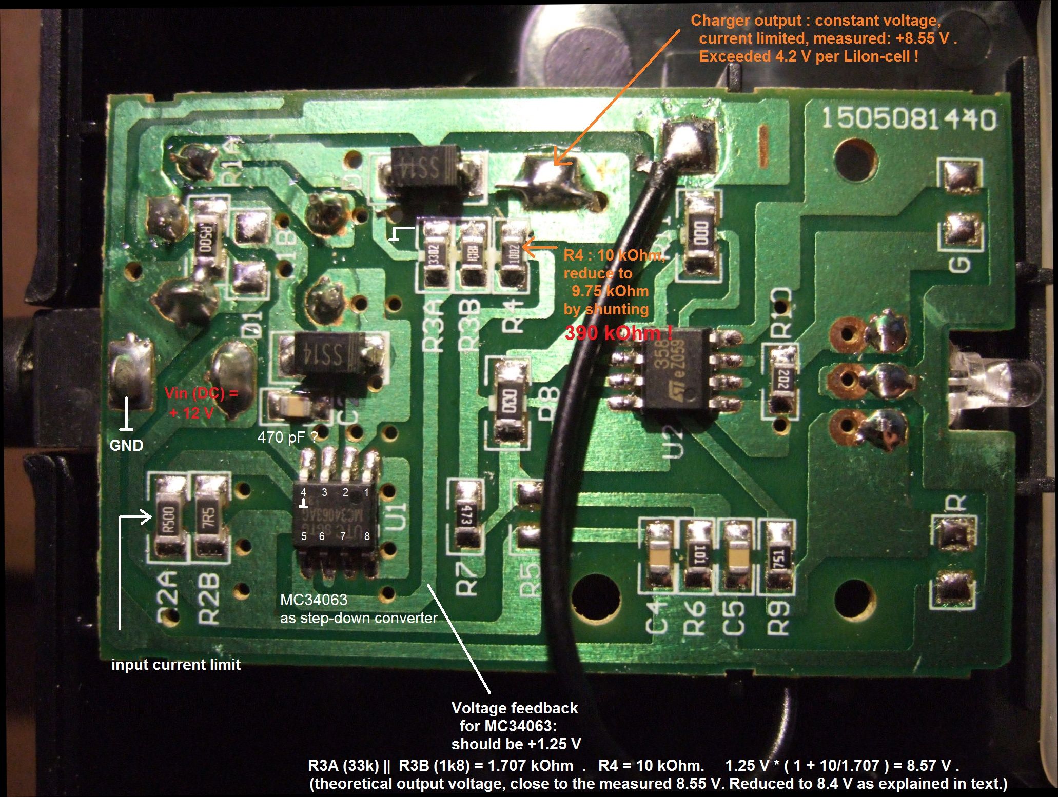
(Click on image to magnify)
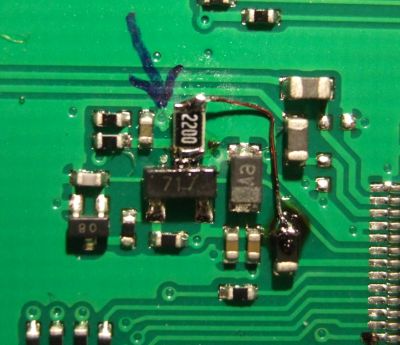
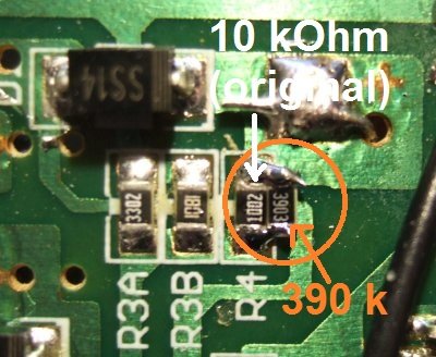 A simple method to bring down the maximum output voltage to 8.4 V is shunting R4 (10 kOhm 'original') with a 390 kOhm resistor.
The 'paralleled' resistance is
1 / ( 1/10kOhm + 1/390kOhm) = 9.75 kOhm,
so with the modified voltage divider, the theoretic output voltage should be:
1.25 V * ( 1 + 9.75 kOhm / 1.707 kOhm ) = 8.39 V .
That's 4.19 Volts per LiIon cell - ok. And indeed, with this modification, the battery stopped 'drawing current' when fully charged,
and the LED turned green after a couple of hours (btw, that's what the LM358 is for, visible in the right half of the photo above). Voila !
An even simpler alternative (instead of 'shunting' R4) would be to remove the 33 kOhm resistor (R3A in the photo shown above).
The theoretic output voltage would then be:
1.25 V * ( 1 + 10 kOhm [R4] / 1.8 kOhm [R3B] ) = 8.19 V .
The two-cell LiIon battery would possibly not be "fully" charged very quickly with this voltage,
but forgetting to remove the radio from the charger would do even less harm then.
As an indicator for a "charged" battery, if you also don't trust the on-screen battery indicator symbol: Six hours after a full charge, without load, the battery voltage was 8.10 V. It dropped by 4 mV after turning the radio on (circa 70 mA load current), thus the internal resistance of 'new' battery (as shipped
from the manufacturer, 2016-12) was about 0.06 Ohms - will keep an eye on this as time passes.
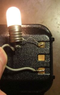
The LiIon battery's charger contacts can 'provide current' during normal operation !
Both the LiIon battery, and the charger appear to have THREE CONNECTORS,
but the center connector isn't connected anywhere (at least, not inside the cheap charger).
There doesn't appear to be a 'smart' circuit inside the battery to protect it from excessive loads.
THIS APPLIES NOT ONLY TO THE CONNECTORS THAT 'FEED THE RADIO' (not exposed),
BUT ALSO TO THE CONNECTORS FOR THE CHARGER,
which are exposed when operating the radio !
Remember this when dropping the RT3 (or MD-380) into your pocket along with the bundle of keys, or other metal objects
- a short across the battery's outer, exposed contacts will possibly ruin it, or even worse.
I didn't want to try how many amps can be drawn from the exposed contacts on the backside of the transceiver.
But as you can see on the right, it's enough to power an ancient filament lamp.
Investing in a diode to protect these contacts against shorts (keyring, etc)
must be asking too much - anno 2018, the same annoyance can still be observed
on the AT-D868UV .
Please see the notes at the end of this chapter -
the backlight intensity is adjustable via software now !
This modification was once done 'in hardware' as described below. If for some reason you need to stick with
Tytera's original firmware, it may still be useful for you - thus the following chapter was not removed.
With Tytera's firmware, the backlight was turned off completely after a programmable timeout. That's not nice, because when this purely transmissive display isn't illuminated from the background,
it's completely unreadable.
A 'permanently' lit display, with reduced intensity but still easily visible, was initially realized with a simple 220 Ohm resistor
connected between collector and emitter of the backlight-switching transistor on the display-/"key"-board.
For reasons only the developers of the original firmware will know, the LCD (TFT) itself is not powered down. So it makes perfect sense
to keep the backlight on, "deeply dimmed". The modification shown below is made on the display board, not on the CPU/RF board:
Left: Display PCB. Middle: Original backlight switch. Right: Modified backlight for "continuous ambient light".
Click on any image to magnify.
The blue arrow points to the transistor's collector. The thin wire on the right photo connects the upper end of the 220 Ohm (SMD)
transistor to the 3.3 V supply for the display. When the backlight is on, there are 3.3 Volts on the collector. When off, 0 Volts. The forward voltage of the white LEDs
is somewhere around 2.9 V, so the 220 Ohm resistor feeds as continuous current of less than 2 mA to the LEDs, which was enough
to read everything on the display in a darkened room (or outdoors). Even the keys were very dimly illuminated - barely visible
but enough to operate them in complete darkness - nice ! The additional power consumption from the battery is neglectable.
Note for developers: The backlight is controlled via pin PC6 by the CPU (STM32F405).
This pin can possibly be reconfigured as PWM (pulse width modulator) instead of GPIO,
but at the time of this writing it was unknown if Timer8 or Timer3 are still available for this purpose.
Having the backlight completely software-controllable (with different intensity settings for "idle" and "active")
would be is great...
Update on the display backlight (2017-01-08)
There are at least two methods for a software-based 'permanent background illumiation' now !
One by Clay, KK6RWR, on github.com/claywalker0929/md380tools,
and one by myself, which can be downloaded from here (right-click and "save as",
then unpack and flash 'experiment.bin' with Tytera's Upgrade.exe or the MD380-tools. ONLY FOR RADIOS WITHOUT GPS SO FAR, i.e. RT3 / MD380.) .
For some reason, the dimmed backlight only worked when the 'Intro Screen'
(menu 'Utilities'..'Radio Settings') was set to 'Char String', not 'Picture' !
A short, bilingual description about the backlight settings is in the zipped archive, and here /
Eine kurze, zweisprachige Beschreibung der Beleuchtungfunktion gibt's im Archiv, oder auch hier .
The firmware in dl4yhf_md380_firmware_experiment.zip/Firmware_XYZ.bin
has a few new items in the setup menu:
Press the 'Menu' key, select 'Utilities', 'MD380Tools'.
scroll down to 'Backlight', then press 'Confirm', and set 'Level Low' / 'Level High' to one of the following:
0 = backlight completely off after the configurable time (only for 'Level Low', without activity)
1 = lowest possible setting, display still readable at night
...
9 = maximum possible brightness (don't use this when running on batteries !)
This sets the brightness used when the radio is idle (no activity for X seconds).
The value of 'X' (in seconds) can be configured in Tytera's 'Radio Settings' menu
(not under 'MD380Tools').
'Level High' cannot be set to 0 (zero brightness), because without backlight you can't
navigate through the menu because the screen is unreadable.
Usually, you will set the 'High' setting higher than the 'Low' setting, but that's up to you.
You will find hundreds of codeplugs for your DMR radio.. so ask the big brother for one in your area.
Below is "mine" (well, not really .. it was copied from DK4WN, and tailored for this area).
Only meaningful for visitors from East Westfalia, Germany, in the area of Herford, Spenge, Enger, Bielefeld;
thus the rest of this chapter in German:
Der folgende Codeplug basiert auf einem "VFO-ähnlichen" Codeplug von DK4WN.
Hinzugefügt wurden einige Analog-Relais (DB0BI, DB0OWL, DB0KB) und beide Zeitschlitze von DB0HFD.
Diese Frequenzen sind zwar ohnehin (mit der Frequenz als Kanalnamen) bereits vorhanden,
aber so werden sie in der "Home-Zone" (OWL) im Klartext angezeigt. Zusätzlich zur Zone "OWL" gibt's auch eine Scan-Liste "OWL",
in der nur die oben aufgeführten, aus "jeder Lebenslage" mit der Gummiwurst zu arbeitenden Repeater enthalten sind.
In der Zone "OWL" bedeuten..
- "DB0HFD-2" = 'DMR über Herford mit Zeitschlitz 2', dort ist i.A. per Reflektor 4050 Ostwestfalen vernetzt (tnx Rolf, DG9YIB);
- "DB0HFD-1" = 'DMR über Herford mit Zeitschlitz 1', dort findet i.A. der "Deutschlandfunk" statt.
Bitte nicht vergessen, den EIGENEN DMR-ID in der CPS (Customer Programming Software von Retevis, "CPS_DMR.exe") einzugeben !
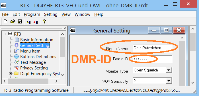
(zum Vergrößern in's Bild klicken)
Wenn im Gerät bereits die 'experimentelle' Firmware geladen ist, geht das auch ohne PC unter
"Menu".."Utilities".."MD380Tools".."Edit DMR-ID".
Für das Anytone D868UV gibt's hier einen ähnlichen Codeplug für OWL.
RT3 Firmware modifications
Each radio is 'calibrated' at the factory, including (but not limited to) modulator drive levels,
and I/Q modulator and demodulator balance. This calibration is important to keep the emission
of unwanted signals as low as possible. Calibration data are stored in a non-volatile memory.
The entire set of 'individual calibration data' can be read out using Retevis' or Tytera's original CPS,
and stored in a safe place. Don't use the calibration data from a friend's radio if you lost yours !.
The 'Test Mode' must be enabled in the CPS by editing 'settings.ini', located in the CPS directory.
Modify the line
testmode=0
to
testmode=1
then restart the CPS.
When connected to the radio via USB, press Control-T.
This opens a tabular display with all calibration values (click on image to see mine, but use yours,
and don't modify anything unless you know exactly what you're doing):
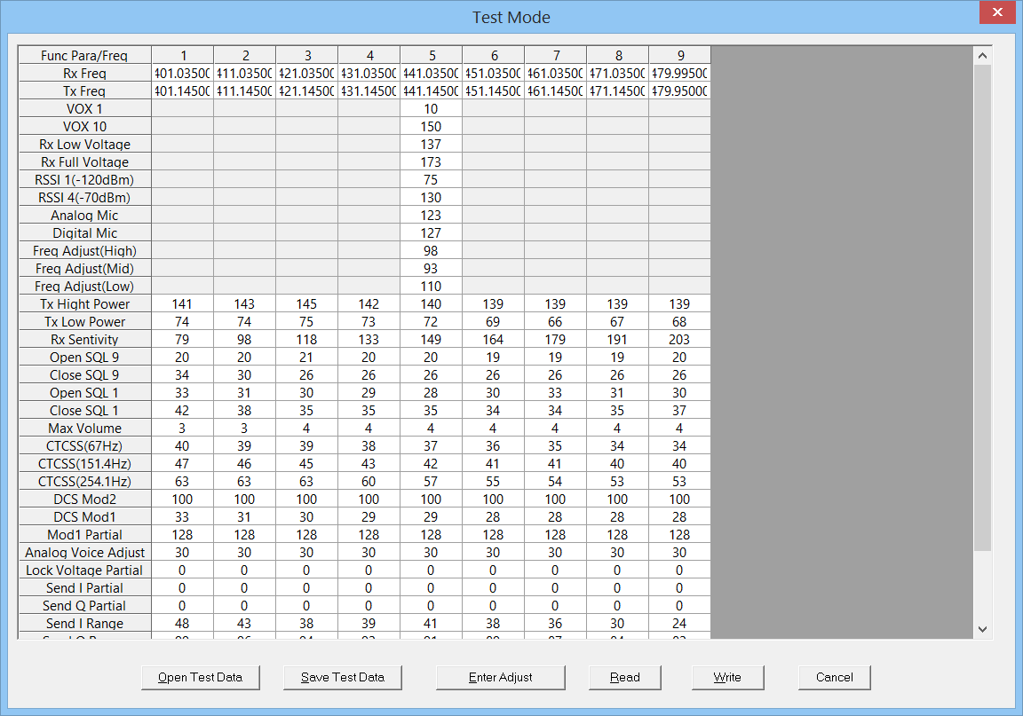 Click on 'Read' to update the data (read from radio), then 'Save Test Data' and store your calibration as a file in
a safe place. On that occasion, also save two screenshots from the 'Test Mode' table (scroll down to the end
to see the rest of the I/Q modulator calibration data, e.g. 'Analog Send I Range', 'Analog Send Q Range').
In the author's radio, there were even different values for different frequencies.
Click on 'Read' to update the data (read from radio), then 'Save Test Data' and store your calibration as a file in
a safe place. On that occasion, also save two screenshots from the 'Test Mode' table (scroll down to the end
to see the rest of the I/Q modulator calibration data, e.g. 'Analog Send I Range', 'Analog Send Q Range').
In the author's radio, there were even different values for different frequencies.
If the radio's calibration gets lost (which hopefully never happens, when playing with the experimental firmware),
you can hopefully load this file again, and write it back into the radio
with the original CPS. As a ham radio operator, you are responsible for the emissions of your radio,
and any responsibility of the manufacturer has already ended when we opened the radio or modified the firmware !
Related subject: Inspecting C5000 register values with the MD380 tools
Besides saving the 'factory calibration', before playing with the 'experimental' firmware (see next chapter) and alternative programming software,
it's necessary to find out what's originally used in the radio (and which "Vocoder" (*) is used in the hardware).
The rig shown above (bought on Ebay in december 2016) showed the following (select 'Menu' .. 'Utilities' .. 'Radio Info' .. 'Versions') :
    Radio Info
 Firmware Ver. :
     D002.034
 CP Ver. :
       V01.32
According to the list at VA3XPR, a radio with this firmware is compatible
with the 'TYT Firmware' D003.020 (for radios with firmware version D002.XXX and D003.XXX). That's the recommended 'normal' firmware for this
radio, seen in December 2016 on the VA3XPR website.
Before 'diving in too deep' (with Travis Goodspeed's 'Experimental' firmware), the old Retevis RT3 firmware Version "D002.034" was replaced
by the Tytera MD-380 firmware (downloaded as 'TYT-MD-380-Firmware-v3.20-old-vocoder.zip' from the VA3XPR site).
The zipped file not only contains the firmware image, but also a windows executable to actually perform the download.
There are a few notes which you must read before updating the firmware (several users have already 'bricked' their
RT3's or MD380's by flashing a firmware that wasn't compatible with the target hardware, and/or the vocoder (*) used in their radio).
Quoted from 'updating.doc' in the zipped archive:
 MD-380 has two versions, new vocoder and old vocoder, so please check version first in the radio,
 check menu-utilities-radio info-versions and if you find the version is D002 and D003,
 it should (be) the old vocoder and the latest firmware is MD380-D3.20,
 while if the version is D013, the firmware should be MD380-D13.20.
Again, to update the firmware without installing the MD380Tools, you will need can use
Tytera's or Retevis' "Upgrade.exe" (windows executable). If you cannot find it on the Retevis or Tytera site:
The updater is also contained in the zipped firmware folders on the VA3XPR site
(for example in TYT-MD-380-Firmware-v3.20-old-vocoder.zip and several others).
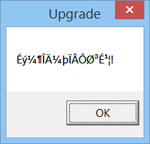
When launching 'Upgrade.exe', we're prompted with this scary dialog:
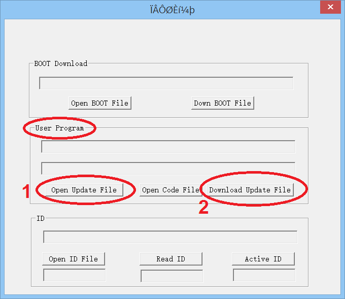
Umm. What next... "Open Update File" or "Open Code File" ? The answer is in "Operation.doc" (for the impatient: 'Open Update File').
That document also explains which buttons to press (on the radio) during power-on to switch it into bootloader-mode:
>
> Press side key 1 and PTT key to turn on the radio, the indicator blinks and open upgraded software .
>
Indeed, the indicator LED near the volume knob now flashes RED / GREEN.
So proceed as explained by the screenshots in "Operation.doc" (the button to click next is "Open Update file", not "Open Code file").
In the screenshot below, the only selectable file was "TYT-TFT-MD380-D3.20.bin", which was a very old firmware.
If you compiled the experimental firmware yourself (from the MD380Tools, in the "dist" folder),
the name could be 'firmware-YYYY-MM-DD-NoGPS.bin' (YYYY-MM-DD = year, month, day of compilation).
Last not least, if you downloaded the 'DL4YHF branch' of the experimental firmware
from here, the name is just Firmware_NoGPS.bin because
I don't keep old compiled firmware with the date in the filename, and there's no firmware for GPS radios in the archive.
Next, click "Download Update File", and keep fingers crossed that all work as planned...
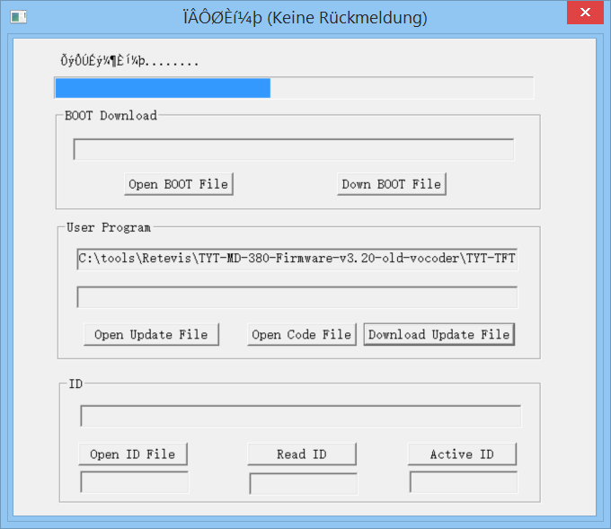 Despite the alarming window title with "Keine Rückmeldung" ('program doesn't respond'), the author was finally greeted by this:
Guess this message means something like "Success!" in Chinese.
Sigh... take a deep breath in, and restart the radio (power-off, and power-on again).
Select 'Menu' .. 'Utilities' .. 'Radio Info' .. 'Versions' again, et voila:
    Radio Info
 Firmware Ver. :
     D003.020
 CP Ver. :
       V01.32
A quick test on the local DMR repeater confirmed the "Tytera" firmware (D003.020) co-operates with the RT3's "old" vocoder (*).
The RT3 was ready for the next step: Install Travis Goodspeed's 'Experimental' firmware... but that's another story.
The master repository (with all sources) is available at github.com/travisgoodspeed/md380tools.
Quite new 'compiled binaries' used to be at
github.com/roelandjansen/md380tools/releases.
For german users, the introduction by DG9VH appeared to be the best startpoint.
For others, there's a step-by-step guide at learn.adafruit.com/tytera-md-380-dmr/updating-md-380-firmware.
Since May 2017, there's a description of the MD380Tools and experimental firmware at md380.org/.
The firmware can easily be flashed into the radio together with an up-to-date DMR user database (more on that later)
with the MD380Tools running in virtual machine running on almost any PC and host OS. See KD4Z/md380tools-vm
- this probably contains all you need so you don't need to read any further in this chapter.
Last not least, there's an active group of developers at groups.google.com/forum/#!forum/md380tools.
i looked at the building steps and ran home screaming for mommy
Patient and brave users (familiar with Linux on a PC or Cygwin on a windows machine) will start with the
MD380 USB Tools's README.
But being impatient, lazy, or both, instead of installing the entire toolchain (to install the prerequisites and compile the 'Experimental' firmware, pulled from github),
I first tried an already compiled binary found somewhere (but that's severely outdated now, thus the link
has been removed here). An easy and less painful way to install an up-to-date version of the 'experimental'
firmware (without the need to compile it yourself) used to be at http://www.foxhollow.ca/DMR/?menu=experimental.
In the meantime, the foxhollow archive also contains the new functions described later on this page.
The firmware update is the same as described in the previous chapter.
After restarting the RT3, the 'Experimental' firmware identifies itself as follows:
(it's still under 'Menu' .. 'Utilities' .. 'Radio Info' .. 'Versions'):
    Radio Info
 MD380Tools Ver.:
     2016-08-12
 CP Ver. :
       V01.32
Again, it could be confirmed (on the local DMR repeater) that the RT3's "old vocoder" (*) is still supported by this firmware.
- (*) Old vs new "Vocoder" ?
-
It later turned out that what the Retevis firmware notes call "vocoder" isn't an AMBE 'vocoder' chip,
since there is no Vocoder hardware (chip) in this radio.
The vocoder, which converts human voice into an amazingly low number of 'bits per second' (and back),
is part of the firmware that runs in the STM32F405 CPU.
Travis even managed to run this software vocoder on a Linux machine (with Cortex emulator), but that's another story.
So what the firmware compatibility notes (by Retevis) call "new vocoder" and "old vocoder" must be something else..
maybe just a 'copy protection' for the patent-encumbered AMBE-core (?).
See also: Travis' clarification about "which firmware to download" at github.com/travisgoodspeed/md380tools/wiki/Download-Firmware .
> If you install the wrong one, you will get a blank white screen at startup.
What was still missing was the DMR user database (users.cvs), loaded into the radio's serial flash chip (W25Q128FV, 16 MByte).
At this stage, it's time to 'start playing' with a more up-to-date version of the patched/experimental firmware.
So install the MD380 Tools on a PC...
If you're not interested in developing the firmware (but simply use it), skip this chapter.
There are much easier ways to build (compile, link, patch) the firmware and to download the user
database. Downloading the experimental firmware is almost trivial (see previous chapter).
So if you're not into this tech stuff, don't read further in this chapter (hello Werner !).
Since no Linux was installed at the author's 'workhorse', and Linux in a Virtual Box couldn't access the host's file system,
I decided to follow the steps explained by Limor, AC2SN (known amongst microcontroller enthusiasts as Ladyada) - see
learn.adafruit.com/tytera-md-380-dmr/updating-md-380-firmware.
I later used another toolchain due to strange problems with 'Cygwin'.. details on that below.
Here just a short list of what you will need, and where to find the prerequisites:
- Install Python Version 2.7.xx from www.python.org/downloads/, if not already present.
Much of the MD380 Tools are "talking to the radio" via USB, and Python scripts implement protocols on top of that.
I installed 'python-2.7.12.amd64.msi' under Windows 8.1 to C:\tools\Python27\, to avoid clashes with another,
incompatible Python version.
If you're new to Python, I suggest to read Ladyada's instructions at her website.
If you installed another Python version, there will be 'trouble ahead'.
If you install a complete Unix-like shell like 'Babun' or MinGW32, you can skip this step
because there are Pythons contained in those packages, or Python can be installed easily
with a single command.
- Install libusb-win32 (I used the 'latest version', 'libusb-win32-bin-1.2.6.0.zip' at the time of this writing).
The Wiki mentions 'Filter Drivers' a 'Device Drivers', and a 'user friendly GUI installer', but doesn't tell exactly where to find that
in the zipped file. I decided to lauch 'bin/amd64/install-filter-win.exe' (for a 64-bit system with an Intel CPU),
and proceeded as descibed here.
- Download PyUSB. Instructions for Python-newcomers like myself
were hard to find on that site, so here's
how I "installed" PyUSB in a Linux-like shell (Babun, more on that later).
- Install Git for Windows (if not already done) as described by Lady Ada.
I installed Git 2.11.0 to C:\tools\Git, but this hopefully doesn't matter if the PATH is properly set.
Install Cygwin (ditched after trouble like "fatal error - cygheap base mismatch detected - 0x180302408/0x1802FF408.", etc, etc, etc, etc)
- Instead of Git and/or Cygwin, install 'Babun' (it's the best Linux-like shell for Windows I've seen so far;
Babun seems to contain most of the essential tools to build the MD380-Tools, except the flakey USB stuff).
I installed it to C:\babun .
- Start the Babun shell, and enter the following command to launch Babun's package manager
(we need 'zip' to avoid errors when building the MD380 Tools later, it's invoked from some of the scripts):
pact install zip
- Install the GCC ARM Embedded toolchain from https://launchpad.net/gcc-arm-embedded
In December 2016, the up-to-date version was gcc-arm-none-eabi-5_4-2016q3-20160926-win32.exe .
I installed it to C:\tools\gcc_arm (without a version and year number in the path name).
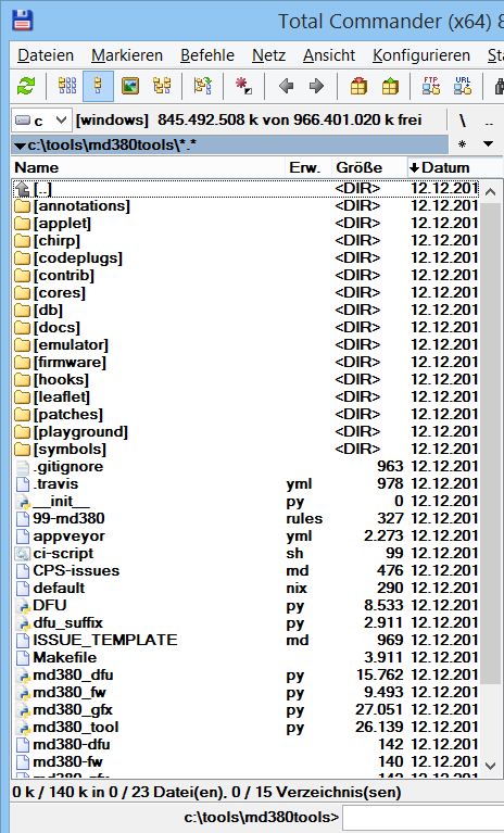 Download and install Travis' MD380 Tools from Github ("Clone or download").
I unzipped all contents from the downloaded file (md380tools-master.zip) into C:\tools\md380tools (see screenshot on the right).
(replaced by letting Git "put things right" via 'git clone' in the command shell, explained further below)
To make sure the scripts, the Unix-like commands, and the cross-compiler for Cortex / ARM can be properly invoked,
check the 'Path' environment variable. It should contain something like the following (but often, it contains a lot more):
C:\cygwin\bin;C:\tools\gcc_arm\bin
(On a german PC, the windoze "Path" variable can be checked and modified in the windoze system control:
"Start".."Systemsteuerung".."System".."Erweiterte Systemeinstellungen".."Erweitert".."Umgebungsvariablen". Aaargh !!)
So back to this chapter's subject: To build (compile, link, controlled by make) the MD380 Tools,
enter the following command in your favourite Unix-like shell.
I assume everything is installed in the directories mentioned above.
We're going to let Git(!) clone the md380tools repository to our harddisk.
This avoids a few headaches later, when modifying the firmware for our own purpose.
Wolf@YHF6 ~
$ cd c:/tools

Wolf@YHF6 /c/tools
$ git clone https://github.com/travisgoodspeed/md380tools.git  # Let's try this ONCE..

git: bash: git: command not found      -> Git doesn't seem to be installed;
                                        let's check if MinGW/MSYS knows "where it is" :
Wolf@YHF6 ~
$ where git
INFORMATION: Es konnten keine Dateien mit dem angegebenen
Muster gefunden werden.  # Before the next step, (re)installed Git for Windows v2.10.2 . Then try again:

Wolf@YHF6 ~
$ where git
c:\tools\Git\cmd\git.exe
c:\tools\Git\mingw64\bin\git.exe

Wolf@YHF6 /c/tools
$ git clone https://github.com/travisgoodspeed/md380tools.git  # only do this ONCE !
Cloning into 'md380tools'...      # no sign of life for several minutes from MinGW

Wolf@YHF6 /c/tools
$ cd md380tools           # this is the directory created and filled by 'git clone'

Wolf@YHF6 /c/tools/md380tools
$ make clean dist  # downloads a lot from the internet, so only do this when 'necessary' (once)
 ...(over 1000 lines of text emitted by 'make' here)...
Wolf@YHF6 /c/tools/md380tools
$
Some of the errors seen during the first attempts to "make clean dist", and how to fix some of them:
- /usr/bin/env: python2: No such file or directory
- Reason: The makefile tries to invoke python2 which didn't exist.
First tried to fix this with an 'alias':
alias python2="python"
This didn't work when "python2" was invoked from make, so
c:\tools\Python27\python.exe was simply duplicated as c:\tools\Python27\python2.exe .
- zip -r dist/md380tools-`date "+%Y-%m-%d"`.zip dist/md380tools-`date "+%Y-%m-%d"`
/bin/sh: zip: command not found
make: *** [dist] Error 127
- Fix: Install the 'zip' command for shell: For MinGW, let its installer install
package 'msys-zip' (ZIP compression utility).
For unknown reasons, this package (zip-3.0-1-msys-1.0.14-bin.tar.lzma)
disappeared from the MinGW Installer's list some day. After re-installing everything:
$ where zip → C:\MinGW\msys\1.0\bin\zip.exe . Ok again.
- make[2]: Entering directory '/cygdrive/c/tools/md380tools/applet'
fatal: Not a git repository (or any parent up to mount point /cygdrive/c)
Stopping at filesystem boundary (GIT_DISCOVERY_ACROSS_FILESYSTEM not set).
- Ignore this (and similar Git-related errors) for now, since we're not going to
create a new Git repo from our modified files yet.
We'll possibly get back to Git-related trouble in future.
- "make" -C applet clean
fatal: Not a git repository (or any of the parent directories): .git
- Ignore this, or pull the repository via 'git clone' (see next Git-related 'fatal' message).
- "make" -C applet FW=D13_020 all
fatal: bad revision 'HEAD'
- More git-related trouble. Should not happen after pulling the md380tools via 'git clone' as explained further above.
Ignore this as long as you don't want to commit or "fork" your own modifications.
You can fix this yourself after studying this book ;o)
- DEBUG: reading "bin/S013.020.bin" (...)
WARNING: Funky header: (...) Trying anyway.
- DL4YHF: No idea what this means, and I didn't feel like finding out myself.
Complete output from 'make clean dist' saved as 'make_clean_dist_output_2016_12_30_after_GIT_CLONE.txt' .
Within a minute or two, "make clean dist" produced a new file 'md380tools-YYYY-MM-DD.zip' in the 'dist' folder (YYYY-MM-DD = date in ISO-format).
The "fresh" compiled and linked firmware image will be in applet/experiment.bin .
 To test it, download that file into the radio as already described ("Upgrade.exe", turn radio on with PTT and the function key above pressed, connect USB, "Open Update File", "C:\tools\md380tools\applet\experiment.bin", "Download Update File") ...
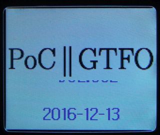
If we haven't messed up the compilation, the radio reboots (after turning off/on)
with the screen contained in the md380tools.
The date of compilation is shown on the 'welcome' screen after power-on.
Most changes are in the 'Utility' menu, under 'MD380Tools'.
Curious people will like to see the C sources (interesting parts are in applet/src)
- see 'More firmware experiments', and subsequent chapters.
Being fed up with switching the USB-drivers back and forth (as explained here),
I tried to download the freshly compiled firmware via md380tools.
The radio must be turned on in bootloader-mode for this purpose (LED blinking red/green).
In this mode, the 'TestLibUsb' utility identified the radio as follows:
bus/device  idVendor/idProduct
bus-0/\\.\libusb0-0001--0x0483-0xdf11     0483/DF11
- Manufacturer : AnyRoad Technology       (!)
- Product      : Digital Radio in USB mode
To update the firmware without rebuilding it, use this command (also works in window's "cmd.exe"):
Wolf@YHF6 /c/tools
$ python md380_dfu.py upgrade dist/md380tools-2017-01-05/firmware-2017-01-05-NoGPS.bin
$ python md380_dfu.py upgrade applet/experiment.bin
Beginning firmware upgrade.
Writing firmware:
0% complete ......
100% complete, now safe to disconnect and/or reboot radio
These *.bin files have been created from the 'merged' original firmware and the patched parts
as roughly described below:
- The ARM linker produces the patched firmware in the form of an ELF file (controlled by applet/Makefile)
- A utility from 'arm-none-eabi' converts the ELF into an 'unstructured', non-scrambled image
(the last one created is in applet/applet.img). This file does not contain any of the original firmware -
especially not the AMBE vocoder, which is one of the key points of DMR.
- One of three similar Python scripts (written especially for a certain firmware variant)
merges applet.img with the 'original' firmware, e.g. applet/merge_d13.020.py, and applies
a lot of 'binary patches' so both firmware parts can co-operate peacefully.
The result is a more-or-less temporary file (applet/merged.img).
This file is unencrypted (thus not suited for Tytera's Upgrade.exe), but it can be
examined with a disassembler (curious readers find the details
here ).
- Another script (md380_fw.py, called from the 'main' make) 'wraps' the *.img into an encrypted *.bin file.
- Yet another script (md380_dfu.py), or Tytera's "Upgrade.exe" can transfer this file into flash memory.
After flashing, turn the radio off and on again. If it doesn't come up with the boot screen within a second,
there's something wrong, quickly turn it off again (who knows what the CPU is doing when 'running in the wild').
Then, try again as explained above (this time with the last tested firmware).
During the author's own additions to the firmware, an RT3 didn't want to start a dozen times,
but when activating the bootloader the LED always began to blink RED / GREEN again (i.e. "bootloader still alive"),
and the radio could always be 'unbricked'.
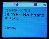
The 'experimental' firmware has a feature to show the callsign and name of the transmitting station on the radio's screen.
- Note:
- This is completely different from looking up the DMR-ID in the normal 'Contacts' list, as most DMR radios do.
The 'Contacts' list, stored along with the 'Codeplug' data, would be limited to a few hundred entries.
 The UHF versions of the MD380/RT3/etc have plenty of space in their serial Flash (16 MByte)
to store the entire database of registered DMR users (over 49000 entries at the time of this writing).
The firmware looks up the received DMR-ID in its Flash memory,
and shows the callsign and operator name on the display beside the numeric ID.
The UHF versions of the MD380/RT3/etc have plenty of space in their serial Flash (16 MByte)
to store the entire database of registered DMR users (over 49000 entries at the time of this writing).
The firmware looks up the received DMR-ID in its Flash memory,
and shows the callsign and operator name on the display beside the numeric ID.
The process of updating the database from the internet, and downloading it into
Flash memory may be cumbersome - especially under Windows..
3.6.1 Updating USERS.CSV under windows
Details on how to get this job done under Windows were difficult to find (in 2016-12 on github/../README.md),
but after collecting bits and pieces of information, it worked (details further below).
- Note:
- You must have the MD380 Tools installed on your system, including a functional Python / PyUSB / libusb
to "talk to the radio", as explained in the previous chapter.
The patched firmware can be downloaded with the "Upgrade.exe" utility by Tytera, but not the DMR user database.
Ed N6YN posted the following fix in the google group:
With either patched firmware v2.032 or D13.020 installed in your radio...
run Zadig, and install libusb-win32 (v1.2.6.0) or (libusb-win32 from:
https://sourceforge.net/projects/libusb-win32/ as described in MD380tools / Windows-instructions.txt)
Once the driver is installed you will see that if you issue a
./md380-tool spiflashid
command, you will received either a # 1 or #2 from the above responses.
Now, execute the "testlibusb-win.exe" file, then click on the Refresh button at the bottom of the popup window.
(Note this file is located in the libusb-win32-bin-1.2.6.0\bin\x86 folder).
Once you click on the Refresh button you will find that if you again issue a
./md380-tool spiflashid
command in the MINGW32 window,
you will receive the proper response from the radio:
      SPI Flash ID: EF 40 18
      W25Q128FV 16MByte
Now you can issue a 'make flashdb' and your CSV file will be properly installed into the SPI Flash.
(remember to perform a "make clean all" in your md380tools/db folder, to update the "users.csv" file)
Details about installing libusb_win32, PyUSB, and run "Python with USB"
in a command shell on windows, are in an extra page on this site
- see Wrong SPI Flash ID,
or "how to transfer the DMR User Database into the radio on Windows".
Wolf@YHF6 ~
$ cd c:/tools/md380tools
         # before the next step, turn radio on and connect USB, and let 'TestLibUsb' run (under windows)
Wolf@YHF6 /c/tools/md380tools
$ make flashdb
"make" -C db stripped.csv
make[1]: Entering directory `/c/tools/md380tools/db'
touch custom.csv
python2 get_special_IDs.py
Fetching list of special IDs from BM master servers.
  .....
./md380-tool spiflashwrite user.bin 0x100000
SPI Flash ID: ef 40 18
W25Q128FV 16MByte
erase 2662838 bytes @ 0x100000
flashing 2662838 bytes @ 0x100000
reboot radio now

Wolf@YHF6 /c/tools/md380tools
$
3.6.2 Using a customized USERS.CSV / user.bin
In a few cases, new registered users appeared 'quite late' in the automatically generated database. To add them 'manually',
load the file 'stripped.csv' (located in md380tool/db) into a good text editor
like Notepad++ (NOT the normal 'windows notepad',
which destroys the Unix line ending format, or doesn't display such files properly). Insert new items, but keep the long list
sorted by DMR-ID. Then save the modified database under a new name 'my_user_db.csv',
to prevent it from being overwritten when rebuilding the md380tools the next time.
Next, invoke the following commands, which are based on the automated 'make flashdb' (which we don't use here because
we don't want to use the automatically downloaded database but "our own"):
Wolf@YHF6 ~
$ cd c:/tools/md380tools

Wolf@YHF6 /c/tools/md380tools
$ wc -c < db/my_user_db.csv > user.bin

Wolf@YHF6 /c/tools/md380tools
$ cat db/my_user_db.csv >> user.bin

Wolf@YHF6 /c/tools/md380tools
$
Remember to switch to a suitable libusb driver first, and 'tickle' the USB port
by running testlibusb-win.exe before launching 'spiflashwrite' - if that's still necessary with the current md380tools:
Wolf@YHF6 /c/tools/md380tools
$ c:/tools/libusb-win32/bin/amd64/testlibusb-win.exe  # DL4YHF tickle USB, must recognize "Patched MD380"
                                                      # before we continue with the next command !

Wolf@YHF6 /c/tools/md380tools
$ python md380_tool.py spiflashwrite user.bin 0x100000
SPI Flash ID: ef 40 18                                # anything else here may indicate a problem
W25Q128FV 16MByte
erase 2618720 bytes @ 0x100000
flashing 2618720 bytes @ 0x100000
reboot radio now

Wolf@YHF6 /c/tools/md380tools
$
See also: How to switch back to the default USB driver (to use the original Retevis / Tytera CPS again).
As already mentioned somewhere, the 'Babun' shell could successfully run all the scripts to build the
patched firmware, but not download the DMR database into the radio, because PyUSB didn't manage
to load any of the libusb-DLLs
("No backend available", details here).
Only the simple command shell from MinGW32 could immediately 'talk to the patched firmware' via USB.
So for most of the 'firmware experiments' described in this chapter, I used the MinGW32 shell (besides an IDE
for embedded software development which I am familar with from the QRL, but that's not required to compile
and link the modified firmware).
If you already installed MinGW32 as suggested here (into C:\MinGW),
start the shell as command (on 'german' windows: "Start", "Ausführen"):
C:\MinGW\msys\1.0\msys.bat
(launches the Linux-like shell). If that doesn't work, check if 'MSYS' is installed via MinGW Installation Manager:
C:\MinGW\libexec\mingw-get\guimain.exe
(install "MSYS", along with the Bash package (Bourne Again Shell) and its documentation).
The Bash-like MSYS/MinGW32 shell identifies itself as 'MINGW32:', followed by the current working directory in the window title.
It helps to increase the 'window buffer size' to 220 characters per line and 2000 lines, so the
shell window can be scrolled back far enough to look for errors and warnings.
In the following chapter(s), text with a black background was copied from the shell.
Commands entered there are sometimes marked in cyan colour (manually, only in this HTML file).
Blue characters are comments or notes, describing what the next step is supposed to do.
Wolf@YHF6 ~
$ cd c:/tools/md380tools

Wolf@YHF6 /c/tools/md380tools
$ make clean
To compile all sources (including those which have not been edited, use 'make all'.
Again, scroll back in your favourite command shell, and watch for errors from the C compiler.
   .....
../../md380-gfx --firmware=patched.img --gfx=0x80f9ca8-poc-gs.ppm relocate
DEBUG: reading "patched.img"
0x80f9ca8 160?ù40
[[253, 255, 252, 0], [216, 218, 215, 0], [26, 27, 25, 0], [195, 197, 194, 0], [0,
], [99, 101, 98, 0], [68, 70, 67, 0], [114, 116, 113, 0], [148, 150, 147, 0]]
?À?À?À?À?À?À?À?À?À?À?À?À?À?À?À?À?À?À?À?À?À?À?À?À?À?À?À?À?À?À?À?À?À?À?À?À?À?À?À?À?
../../md380-gfx --firmware=patched.img --gfx=0x80f9ca8-poc-gs.ppm relocate
DEBUG: reading "patched.img"
0x80f9ca8 160×40
[[253, 255, 252, 0], [216, 218, 215, 0], [26, 27, 25, 0], [195, 197, 194, 0], [0, 2, 0, 0],
···························································································
···························································································
···························································································
···························································································
·····························································122···322·····················
···········································131···············3445··644·················115·
···777772222289a························b7444448a··47········3445··644·············39444444
···cd444dccc824441····················52442e15e44e948········3445··644············e444865a7
·····7445·····a4446··················1444f·····574448········3445··644···········d4475·····
·····7445······f442·················5444a·······54448········3445··644··········e448·······
·····7445·······4443················944b·········3448········3445··644······
As a C developer, for a few quick experiments, it's tempting to simply modify a few sourcefiles (mostly
in 'applet/src', some in 'playground/src'), rebuild everything, and try if it
works (don't expect you can debug on the target - your search for a standard JTAG- or SWD-
connector in the RT3/MD380 will be in vain..). But consider this: The MD380 Tools
are a 'River of Constant Change' - you may inadvertedly overwrite 'your' *.c file
when unzipping the next version from Github ! You don't want to commit+push a half-cooked egg
on Github. There are advanced ways to get around this (locally, using Git).
Anyway I (that's DL4YHF) decided to give modified C-modules a new name, or
at least move them to a directory that doesn't conflict with the existing
MD380tools directory structure.
The firmware building process is quite different from 'classic' software development.
Instead of letting the linker 'decide' on which address a function, variable,
stack, heap etc shall be located (possibly aided by a scatter-loading file,
as my favourite development system likes to call it), the patched RT3 / MD380
firmware must co-operate with the original firmware, which still resides at fixed
addresses (this especially applies to the HR_C5000 chip interface and the
software-based AMBE-compatible vocoder).
To get familiar with the firmware modules (written in C), a short overview was written
in plain text. This was later converted into HTML, with links to the C source.
Right-click on the following link, and 'save target as' md380_fw.html in the 'docs'
directory of your md380tools. Don't just "follow the link" below and save the page after
it was loaded into the browser - at least Firefox stupidly converted the relative
links inside the file to absolute ones (directing to the URL from where the page was downloaded),
which renders the purpose of the 'links to the C files' (stored on your harddisk) useless.
md380_fw.html
(in December 2016, the 'master' of the above file was located at http://www.qsl.net/dl4yhf/RT3/md380_fw.html )
At the time of this writing (2017-03-10), the Morse output is far from being perfect.
For example, it fails to retrieve certain menu items, and sometimes interferes with message beeps
generated by the original firmware.
But for visually impaired hams, it may already be useful as-is.
The "narrator" (in German: "Vorleser") reports..
- the currently selected channel number or -name, when turning the channel knob
- the menu title and text from the currently selected item, after entering a menu
- the text from the new item, after pressing an up/down key in a menu
- reports either channel name or -number when pressing a configurable side button,
or the menu title followed by the text read from the currently focused item
(selected line in the menu, config option, 'enable / disable', etc)
- (only 'on request' via sidekey) the contents of the text console / Netmon screen,
for hardcore CW enthusiasts.
- (also 'on request', when configured for 'verbose' output) the battery voltage
As most firmware extensions, Morse generator and narrator are configured
in the MD380Tools menu:
      Menu
  Contacts
  Scan
   ...
  Utilities
|
|
→
|
    Utilities
  Radio Settings
  Radio Info
  Program Radio
  MD380Tools
|
|
→
|
   MD380Tools
   ...
  Side Buttons
   ...
  Morse output
|
|
→
|
 Morse output
  Mode
  Speed [WPM]
  CW pitch [Hz]
  CW volume
|
|
MD380Tools menu with configuration of the Morse 'narrator'
      Mode
  off
  short
  verbose
  test/future
|
|
|
|
|
  CW pitch [Hz]
  400
  650
  800
   ?
|
|
|
   CW volume
  low
  medium
  high
  auto
|
|
Because it's difficult to activate the Morse output if you can't see the menu,
here is an alternative method to turn it on initially, with the default settings (18 WPM, 650 Hz):
- Turn the radio off
- Press and hold the red 'BACK'-button in the upper right corner of the keypad
- Turn the radio on again
- Release the 'BACK' button when you hear the name of the currently selected channel in Morse code.
Since 2017-05-14, when turning on the radio as described above, the default settings for the Morse output
are restored. If the red button was pressed by accident, you've got five seconds to release it
to avoid restoring the default (Morse-) settings:
 Set Morse Defaults ?

  Hold red key down
  to confirm.
|
|
5
secs
later
→
|
 Morse defaults set.

  Adjust parameters
  in the setup menu.
Release key now. |
|
Due to some problems getting the 'Narrator' to work properly in the original menu
(including the MD380Tools submenu), the alternative menu may be easier to use for visually impaired operators. More on that in one of the next chapters.
In both menus (original menu by Tytera and the alternative menu), fixed text and titles
are sent with a slighly lower pitch in Morse code.
The following modes have been implemented so far:
- off
- The narrator doesn't start talking automatically.
But it can still be activated "on request", if one of the programmable Side Buttons
has been set to 'Morse Narrator'. Pressing the 'Narrator'-button will announce
the current channel (name), or menu title followed by the currently selected menu text.
So if you didn't get everything on the first time, press the button again to repeat the announcement.
How to configure a sidebutton to start the 'Narrator' will be explained later.
- short
- Output text as short as possible.
When turning the channel encoder, reports the channel number.
- verbose
- Reports more details.
When turning the channel encoder, reports the channel name.
- test/future (or "DevOnly")
- Sends out some debugging info in Morse code. Only intended for development.
Many of the front buttons were already occupied by the experimental/optional Netmon
feature. At the time of this writing, the two side buttons (above and below the PTT) were configurable
for approximately 25 different functions. Thus, there is no 'fixed' key
available to start a longer Morse output on request.
Solution: A 26th function was added to the 'programmable' side buttons.
To request a 'long report' from the narrator (e.g. with channel name, zone, battery voltage,
and who-knows-what-else), one of the side button functions must be configured
as shown in the example below:
   MD380Tools
  Set Talkgroup
  Mic bargraph
  Experimental
  Side Buttons
|
|
→
|
  Side Buttons
  Top Pressed
  Bottom Pressed
  Top Held
  Bottom Held
|
|
→
|
  Top Pressed
  1750 Hz Tone
   ...
  Morse Narrator
  Morse Repeat
|
|
Configuration of a Side Button to start telling a 'long story' in Morse code.
Not required for normal messages like channel name and menu announcement !
The 'story' told when pressing the side button configured this way depends on the
current radio state, and the configuration of the morse output.
In verbose mode:
- On the main screen (i.e. not in a menu):
- Channel name, zone name, battery voltage. Example:
DB0HFD-2 zone OWL vbat 8.2 V
- In a menu:
- Menu title (text with gray background), currently selected item. Example:
utilities radio settings
- In any of the Netmon screens:
- Reads out the entire screen (console) in Morse code.
This may be a 'really long story' - only for CW freaks, or for code practice.
Any message ('long story' requested via sidebutton or 'automatic report' of channel or menu item)
can be stopped by a very short press of the PTT key. This also prevents sending out
an over-modulated Morse code message over a repeater by accident.
Another programmable side-button function (Morse Repeat) repeats the previous
automatically reported message, e.g. channel name or current menu item.
Unfortunately, the 'beep' (tone) generated by the CPU isn't routed via the
analog volume control pot to the speaker output. Thus the output volume cannot
be controlled directly via the potentiometer.
At the moment, three different volume levels can be selected from the menu.
They are realized by different PWM duty cycles, which makes the tone rich in
harmonics ("squeaky" like the sidetone in some older electronic keyers).
A clean sinewave may be possible in a future version, at the expense of a higher
CPU load (over 10000 interrupts per second).
A voice output will not be possible with this radio - it's RAM is too
short to synthesize audio ("text to speech"), so take this as an opportunity
to learn Morse code. For fun, start at 15 or 18 WPM, and after some practice,
try 22 or 30 WPM (words per minute).
A preliminary version (with compiled binary for MD380 / RT3 without GPS only)
is in the zipped archive with the
'weak backlight experiment'.
The principle (in the modified firmware) is here.
Since the 'Morse narrator' has been added to the main branch of Travis' MD380-Tools,
it is listed along with the other features of the patched firmware at
md380.org since May 2017. But development goes on - see next chapter.
In addition to the default 'green key' menu (including the MD380Tools menu),
an extra menu was added in the patched firmware. Unlike the original menu,
the complete sources for this menu are available, so it was much easier to
integrate the Morse output here. In fact, some parameters can only be modified
in this menu if you cannot see the display.
The alternative menu, aka "app menu" can be opened by pressing the red 'BACK'
button while on the main screen.
The main differences to the original menu are:
- no deep nesting, as few submenus as possible
- instead a fast-scrollable list, cursor up/down keys with auto-repeat
- current settings immediately visible without having to press ENTER
- seamless integration of the Morse output (see previous chapter)
- designed for simplicity, no whistles and bells (mainly "text only")
- but with a freely adjustable colour scheme and a few other goodies
At the time of this writing, the alternative menu's main page contained
the following items (new items will appear at the end in future):
 Chnl DB0HFD-1
 Zone      OWL
 Cont TG262-DL
 TkGrp     262
 [ 1 >---------
 Test/Setup
 Netmon
Exit |
|
Main page of the alternative menu, aka 'app menu' or 'red key menu'
Horizontal lines beginning with a digit mark the begin of a new section or topic.
Pressing a digit key warps to the section. This makes navigation much easier and faster
than in the original menu, once you saw the section numbers when scrolling through
the menu. In the example shown above, press '1' to jump to item 'Test/Setup',
followed by ENTER (green key) to open it (or, for items with editable parameters, begin editing).
Some menu items will switch to a different screen (e.g. 'Netmon').
The red BACK key aborts editing (and restores the original value), or switches back
to the parent menu, or returns from the alternative menu to the main screen.
Some of the items in the Test/Setup menu are shown below. At the time of this writing,
the entire application-menu was in a very early stage of development, so the final result
may be quite different.
 Setup:Back
[ 1 Backlight >--
 Level Lo    1
 Level Hi    2
 Time/sec   15
[ 2 Morse >------
 Mode  verbose
 Speed/WPM  35
 Pitch/Hz  650
 Volume   auto
[ 3 Colours >----
 Colour Scheme
 Foregnd  EE11
 Backgnd  38C3
 Sel/nav fg ..
 Sel/nav bg ..
 Editor fg  ..
 Editor bg  ..
[ 4 Test/Debug>--
 Hexmon,Netmon,..
Setup:Back |
|
Test / Setup page in the alternative menu
To be continued ...
For DMR, it's sometimes helpful to change the talkgroup number on-the-fly.
Technically, the talkgroup your radio transmits to is a group call,
and you could program extra channels for the same repeater frequency with different
talkgroups. There has also been an item in the MD380Tools menu (Set Talkgroup)
for some time, but it was a long way to get there (green 'Menu' key, Utilities,
scroll to MD380Tools, enter, scroll to Set Talkgroup, ..).
Alternatively, one of the side buttons can be configured to jump directly
into the alternative menu where a new talkgroup
can be entered on-the-fly for transmission:
 Chnl DB0HFD-1
 Zone      OWL
 Cont TG262-DL
 TkGrp     262
 [ 1 >--------
 Test/Setup
 Netmon
Exit |
|
→ |
 Chnl DB0HFD-1
 Zone      OWL
 Cont TG262-DL
 TkGrp     262
 [ 1 >--------
 Test/Setup
 Netmon
Exit |
| → |
 Chnl DB0HFD-1
 Zone      OWL
 Cont TG262-DL
 TkGrp    0001
 [ 1 >--------
 Test/Setup
 Netmon
Exit |
|
→ |
 Chnl DB0HFD-1
 Zone      OWL
 Cont    TG 1*
 TkGrp       1
 [ 1 >--------
 Test/Setup
 Netmon
Exit |
|
Menu item 'Talkgroup' when navigating (leftmost image),
in increment/decrement mode, in direct input editing mode,
and after finishing input (rightmost image).
If necessary (e.g. when not opened via sidekey), press Enter (green key)
to switch from 'navigation' (with the whole line marked) into 'edit' mode.
There are different editing modes (not only for the talkgroup):
- 'increment / decrement' edit mode
Cursor up/down increments or decrements the value.
Best suited when the value shown in the menu is only a few steps away
from the desired (new) value. In most cases, this is the default.
In this mode, the entire edit field (e.g. "number") is marked.
- direct input mode
As soon as a digit key is pressed, the edit field switches from
'increment/decrement' into direct input mode. Since the MD380 has no cursor left/right keys,
the up/down keys are now used to control the cursor within the edit field.
In this mode, only a single digit (or character) is marked.
When pressing a digit, the character 'under the cursor' will be overwritten,
and the cursor moves right by one character.
If the automatic Morse output is enabled, the new value will be reported
after each change. Only after finishing input (by pressing Enter / green key),
the entire menu line, including the text before the value, is sent in Morse code.
- Note
- A talkgroup entered this way will be lost when turning the radio off.
It is not stored permanently as part of the channel in the
radio's Flash 'codeplug' memory. Switching to a different channel
also causes the radio to load another talkgroup number from the codeplug again.
Thus the term 'Ad-hoc talkgroup', even though the text
shown in the alternative menu is only 'TkGrp'.