The starting point of
the considerations was the question of how much "counterpoints" a
vertical antenna actually needs. The design of the horizontal 90 °
angle dipole described here is also very popular as an "upper-and-outer"
especially for portable fans and only comes with such a counterpoise.
This is one reason to take a closer look at this type of antenna and
to develop a version covering 10-40 m bands.
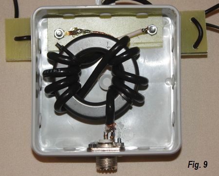
If simple solutions
are chosen as the 1: 9 broadband Un-Un ("Magnetic Balun"), so you
still need an antenna tuner and may have significant losses but
usually only as a monoband version uncomplicated build.
The most well-known
vertical radiator is probably the lambda/ 4 Marconi antenna, which
requires a ground network, which must be very expensive for a good
efficiency. Now the Marconi antenna is comparable to a dipole, the
second half of which is replaced by the reflecting earth surface. It
is easier if you actually build 2 x lambda/ 4. However, then the
question arises, where to go with the second "leg" if the total
height for a true vertical dipole with a half-wavelength is not
reached. The classic solution is called "groundplane antenna", in
which the counterpoise consists of 4 lambda/4 long sections at right
angles. But does that really have to be so complicated?
Theoretical
considerations
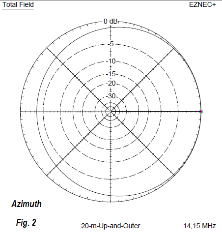
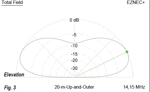
The advantage of a
vertical antenna is that, assuming one builds up and has a free
environment, it provides a 360° radiation at a relatively flat
elevation angle. This can sometimes be better for DX than a
horizontal dipole, but in which - especially due to lack of
structure height - the elevation angle is larger and thus less
favorable. The minimum for a perfect round radiation are two "counter
poises" in opposite with 180 ° distance arrangement. This version,
developed as "inverted T-antenna", was described by me in [1]. But
it is even easier, if one accepts that the all-round radiation is
not perfect.
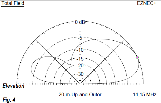
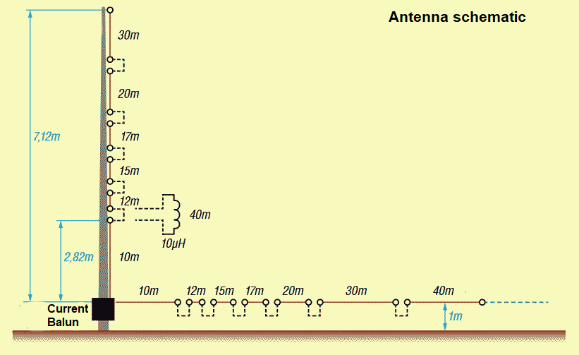
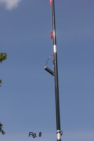
The vertical angle
dipole is obtained by bending the classic half-wave dipole in the
middle and leading one section vertically upwards and the other
parallel to the ground. In free space, this angle dipole has an
impedance of 45 , the length must increase compared to the
stretched normal form by about 3%.
If you
build them strictly symmetrical with equal lengths for the vertical
and horizontal parts, an interesting effect occurs. The capacitive
load occurring through the ground leads to an asymmetry of the two
mechanically equal antenna sections and the impedance decreases. As
a result, the 50-Ohm-point on the counterweight moves electrically
further outward. This applies to the case where e.g. such an antenna
for the 20-m-band is configured so that the feed point is 1 m above
the ground and also at a corresponding height of the horizontal part
is arranged.
Analyzation with
EZNEC
If a symmetrical antenna has an impedance <50 Ohm, then one can
optimize for a higher radiation resistance by arranging the feed
point off-center. This is known from the FD-4, in which the feed
takes place at a point of about 300 and thus the antenna is
divided into two unequal length sections.