|
by Dipl. Ing. Robert Tyrakowski , DK7NT Dr. rer.nat. Horst Schütze, DF7HSA Dipl.Ing Klaus Osterschek, DB4MP OVERVIEW Characteristic
data Table
1: Some
frequency standards
|
Last
update: 27-September-2001
PART 1 Controlled Reference Oscillator (CRO) biased by GPS & ZDF (TV-based references)
byDipl. Ing. Günter König, DJ8CY
Dipl. Ing. Robert Tyrakowski , DK7NT
Dr. rer.nat. Horst Schütze, DF7HSA
Dipl.Ing Klaus Osterschek, DB4MPTranslation by Lutz Hannig, DL9GI (Draft 30 May 2001) [email protected] OVERVIEW
Determining exact frequencies has always been the claim of radio and measurement technology. This article reports details of the development of a high-precision, GPS/TV controlled reference oscillator, which is able to improve the frequency stability of its own station as well as the beacon station. The equipment can be used for measuring oscillator stabilities as well and is fit for the home brewer. Both the GPS and the TV/FBAS - Signal (i.e. German TV - ZDF) can be used for a frequency/time reference.
Characteristic data
The stability of the oscillator frequency can be derived from the absolute value, respectively, from the deviation,df, to the value, f, by comparing it with a frequency/time reference. The relative stability of the oscillator frequency is usually formed by the quotient (df/f ). This representation is independent of the initial frequency of the frequency processor and allows a quick rating in respect to the final frequency. For instance, in the worst case, the oscillator of a 24 GHz beacon has a relative stability (df/f ) of 10exp-7, which leads to a frequency setoff of about df=2.419kHz at 24192.900 MHz . Finding such a beacon with the DSP within the SSB bandwidth can quickly turn into a problem.
The oscillator drift is subject to physical principles. The offset ratio normally depends on environmental conditions (such as temperature, static pressure, magnetic fields, etc.) and the aging process. In order to come to a reliable statement about the above-mentioned oscillator stability, a precise frequency, or time standard, is essential. In measurement technology, the term 'frequency standard' is defined in such a way that the outgoing signal is equivalent to an AC of constant period with almost no environmental influence. Primary and secondary frequency standards are known. At primary standards, the absolute value of the frequency is calculated from physical laws exclusively and needs no adjustment in respect to the outgoing frequency. At secondary standards, the absolute frequency is brought to the final frequency by comparing it to a primary standard. The secondary standard produces, within narrow tolerances, a frequency of high precision, which still depends on environmental and aging processes. Therefore, a cyclic calibration is inalienable.
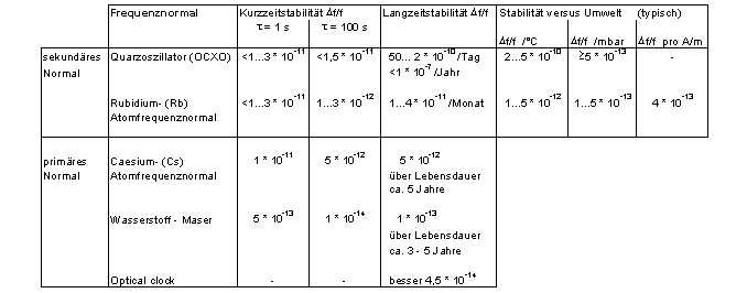
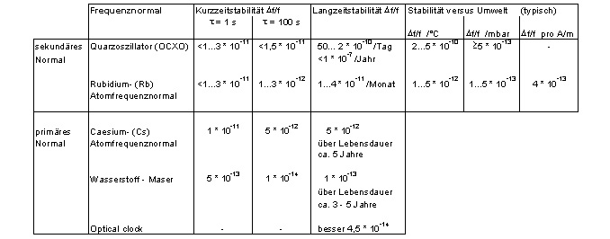
Further classification of oscillators differs between long and short-term stability. Long-term stability is the precise rate over a longer period of time (typ.>105s). Short-term stability is given for the characterization over a certain time period, which is usually between 1 and 1000s. In principle, the observation time specified has to be given. By taking a multitude of short-term stability measurements, conclusions to all noise and drift processes versus time on high precision oscillators can be given by the so-called Allan Variance. A short comparison (Fig. 1) between the efficient principle, the thermically-stabilized quartz-oscillator and the atom-standard show the achievable stabilities. Using such modern processes as laser technology, found under the key words 'laser cooling' and 'optical clocks', relative stabilities of 10exp-14 are reached - which is true, for instance, on the basis of magnesium with a stability of 4,5*10exp-14.
Table 1: Some frequency standards
CRO PROPERTIES
Also Rb and Cs atom standards became near at hand for ham radio operators, this article tries to present a cost-efficient solution. The main goal was to reach stabilities of a Rubidium standard leading to the 'Controlled Reference Oscillator (CRO). Its essential part, the phase counter, can be used as follows:
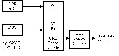
- Gauge without oscillator control for evaluating thermal qualities, stabilities and working conditions of oscillators up to 130 MHz (Fig. 1).
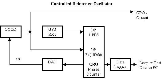
- Frequency loop for binding oscillators of all types and up to 130 MHz to a high-grade reference signal (Fig. 2) .
For these measurements, the following reference signals can be used:
- GPS, 1 PPS - Pulse
- TV, FBAS - Signal (i.e. German ZDF)
- Other references based on 1 PPS with asymmetrical pulse duty factor.
Figure 1: Simplified block diagram for oscillator measuring
Figure 2: Simplified block diagram - frequency loop
TEST PRINCIPLE
The CRO measuring method has been known of for years and was released, amongst others, in a publication of the PTB (Physikalisch Technische Bundesanstalt, Germany) in 1994 [1]. Although it primarily describes the use of the ZDF TV signal as a reference, the same measuring method can be used for the 1 PPS signal of GPS receivers and similar signals.
The test principle, as set forth in Figure 3, is based on a counter (phase counter, i.e. with 100 MHz), which counts the distance between two flanks. While the first flank opens the gate of the counter, the phase counter begins to count in 100 MHz increments. As the second flank closes the gate, the counting is halted. Was the phase counter cleared in advance, the counter would store a value equal to the time distance between two flanks in a resolution of +/- 10 ns.
In the case of the CRO, the first flank for opening the phase counter is produced with the frequency of the test oscillator. Therefore the oscillator-frequency (fx) is figured with a divider (fx -divider) down to 1 Hz. The second flank for closing the gate is either the 1 PPS signal of the GPS receiver or the VSYNC signal extracted from the FBAS signal of a TV tuner. Decisive only for the measurement is the next flank of the PPS or VSYNC signal after the opening of the gate circuit by the first flank.
For the phase counter cannot have any desired length (here 22 bit with a dynamic of 16 bit), a synchronizer takes care that the distance between two flanks does not exceed certain limits to prevent the counter from overflowing.
If the distance between two flanks never varies, the phase counter stores the same values for each measurement. Only the jitter of both flanks can produce small differences in the result, which can be safely ignored if averaged over time. So, if the phase counting value remains constant, both frequencies are the same.
Should the distance between the two flanks of measurement decrease, the phase counting value also decreases. This now means that fx has a smaller frequency than the reference-frequency.
Alternatively, if the distance between two flanks of measurement increases, the phase counting value also increases, meaning that fx now has a higher frequency than the reference frequency.
The absolute value of the phase counter in respect to one measurement is irrelevant. Only the difference of one value of the actual measurement to the value of the preceding measurement is constantly summed up and displayed. The diagram can be weighted by a statistical method, the so-called linear regression. The result is a straight-line representing the mean value of all measurements. The gradient of this straight-line represents the difference of both frequencies. It can later serve as a reset value for a proper control loop.
Figure 3: Test principle
SUBASSEMBLY AND COMPONENTS
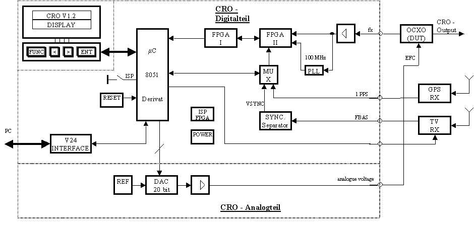
As shown in the block diagram, the CRO consists of several subassemblies. The main two parts, the analogue and digital part, are described here. Due to a widespread offer of commercial or home brewed oscillators, which can be integrated, and in order to ease the home brew reproduction of the CRO - the oscillators, which are regulated by the CRO, were not part of this project. We thought this is an advantage for the user.
For the follow-up control of the oscillators is managed with a very small change of an analogue voltage (with the HP OCXO 10811 a voltage gain of 1mV is equivalent to a frequency change of 1*10exp-11) and furthermore to avoid interference a splitting of analogue and digital-part was chosen. The digital part, with one exception, contains all digital parts of the CRO, while the analogue part, holding all analogue components, can be placed close - but spaced from the oscillator. The voltage for the analogue part can be fed by the power supply of the oscillator, thus allowing the switch-off of the digital-part while the oscillator and the analogue part continue working. A serial connection jack is responsible for the connection of the analogue and digital part.
Figure 4: CRO subassemblies
DIGITAL HARDWARE
If the reference signal and the signal of the oscillator to be measured are both digitized, the rest of the measuring, the evaluation and the calculation of the reset value can also be done digitally. The peak calculation of the CRO digital platform (Fig.5) is managed by a Temic/Atmel Micro controller [2], a 8051 derivat which doesn't need a data logger and houses an 'in system' programming device. A reset-IC safeguards a prompt start after the power supply is switched on, which should lie between 7-12 volts and be stabilized by a series regulator. The connection to the outer world is realized by a RS232 series connector by Maxim [3]. For the operation a connector for a 2*16 digit long LCD-display is present. All relevant data, i.e. preset data etc., are stored in a non-volatile EE-PROM. To keep the expense on discrete component parts as low as possible, for the realization of various counters and manifold logics so called FPGA's (Field Programable Gate Arrays) were used. The memory of the FPGA's can be programmed with a free developers-software and with a home brewed programming device fed into the board. All fast logic elements were combined in a FPGA of higher quality. The slower logic is combined in a cheaper, somewhat bigger FPGA. As mentioned above, for the reference can be used either the digital 1 PPS signal of a GPS-receiver or the VSYNC-signal of a TV-receiver. The 1 PPS-signal is directly fed into the gate-logic of the phase counter, whereas the VSYNC_signal has to be derived from the FBAS-signal. For that purpose the impulse decoder from the Gennum company [5] is integrated on the CRO-board. Of course the channel switching of the TV-tuner can be done directly from the CRO. The signal of the oscillator to be measured is led through two amplifier stages to an almost TTL-level and then fed into the measuring device. A special PLL-IC by the ICST company [6] creates from the frequency of the oscillator a further frequency of ca. 100 MHz. This frequency is used by the phase counter to measure the distance between Start/Stop flanks. This method has in comparison to DIL-oscillators the main advantage that a high precision 100 MHz-signal is at hand which is synchrone to the frequency to be measured. The absolute frequency in this respect is of minor importance for the measuring principle is based on 1s resp. 1/50 s. Drift effects of a DIL-Oscillator, however, would have a distinct effect on the result.
Due to the fact that mainly compact components are used a relative small and price worthy, double sided board could be developed. It has only two specialities - to avoid local interference special care in the layout was taken in separating the PLL-ICs from the rest of the digital part. The digital part itself fits into a standard tin-plate box. The leading out of the flatbandcables for the LCD-display and the small keyboard can easily managed by cutting the metal twice on one side (in size of the flatband) and then bending the small metal tongue for the opening. All the other inputs and outputs can be done with lead-in filters, while all HF-inputs are managed by Teflon-lead-ins.
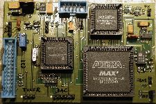
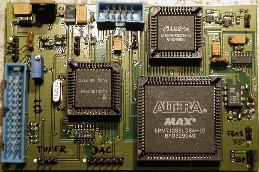
Figure 5: CRO Digital Part
