|
by Dipl. Ing. Robert Tyrakowski , DK7NT Dr. rer.nat. Horst Schütze, DF7HSA Dipl.Ing Klaus Osterschek, DB4MP OVERVIEW Characteristic
data Table
1: Some
frequency standards
|
Last
update: 21-August-2001
Controlled Reference Oscillator (CRO) biased by GPS & ZDF (TV-based references)
byDipl. Ing. Günter König, DJ8CY
Dipl. Ing. Robert Tyrakowski , DK7NT
Dr. rer.nat. Horst Schütze, DF7HSA
Dipl.Ing Klaus Osterschek, DB4MPTranslation by Lutz Hannig, DL9GI (Draft 30 May 2001) [email protected] OVERVIEW
Determining exact frequencies has always been the claim of radio and measurement technology. This article reports details of the development of a high-precision, GPS/TV controlled reference oscillator, which is able to improve the frequency stability of its own station as well as the beacon station. The equipment can be used for measuring oscillator stabilities as well and is fit for the home brewer. Both the GPS and the TV/FBAS - Signal (i.e. German TV - ZDF) can be used for a frequency/time reference.
Characteristic data
The stability of the oscillator frequency can be derived from the absolute value, respectively, from the deviation,df, to the value, f, by comparing it with a frequency/time reference. The relative stability of the oscillator frequency is usually formed by the quotient (df/f ). This representation is independent of the initial frequency of the frequency processor and allows a quick rating in respect to the final frequency. For instance, in the worst case, the oscillator of a 24 GHz beacon has a relative stability (df/f ) of 10exp-7, which leads to a frequency setoff of about df=2.419kHz at 24192.900 MHz . Finding such a beacon with the DSP within the SSB bandwidth can quickly turn into a problem.
The oscillator drift is subject to physical principles. The offset ratio normally depends on environmental conditions (such as temperature, static pressure, magnetic fields, etc.) and the aging process. In order to come to a reliable statement about the above-mentioned oscillator stability, a precise frequency, or time standard, is essential. In measurement technology, the term 'frequency standard' is defined in such a way that the outgoing signal is equivalent to an AC of constant period with almost no environmental influence. Primary and secondary frequency standards are known. At primary standards, the absolute value of the frequency is calculated from physical laws exclusively and needs no adjustment in respect to the outgoing frequency. At secondary standards, the absolute frequency is brought to the final frequency by comparing it to a primary standard. The secondary standard produces, within narrow tolerances, a frequency of high precision, which still depends on environmental and aging processes. Therefore, a cyclic calibration is inalienable.
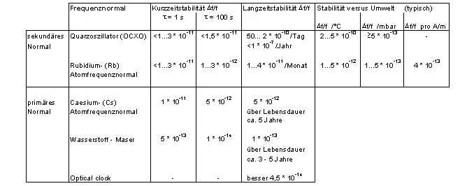
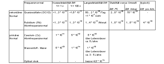
Further classification of oscillators differs between long and short-term stability. Long-term stability is the precise rate over a longer period of time (typ.š 105s). Short-term stability is given for the characterization over a certain time period, which is usually between 1 and 1000s. In principle, the observation time specified has to be given. By taking a multitude of short-term stability measurements, conclusions to all noise and drift processes versus time on high precision oscillators can be given by the so-called Allan Variance. A short comparison (Fig. 1) between the efficient principle, the thermically-stabilized quartz-oscillator and the atom-standard show the achievable stabilities. Using such modern processes as laser technology, found under the key words 'laser cooling' and 'optical clocks', relative stabilities of 10exp-14 are reached - which is true, for instance, on the basis of magnesium with a stability of 4,5*10exp-14.
Table 1: Some frequency standards
CRO PROPERTIES
Also Rb and Cs atom standards became near at hand for ham radio operators, this article tries to present a cost-efficient solution. The main goal was to reach stabilities of a Rubidium standard leading to the 'Controlled Reference Oscillator'(CRO). Its essential part, the phase counter, can be used as follows:
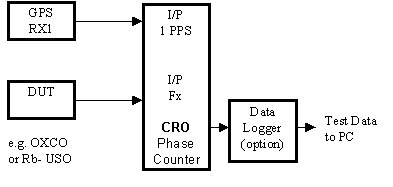
- Gauge without oscillator control for evaluating thermal qualities, stabilities and working conditions of oscillators up to 130 MHz (Fig. 1).
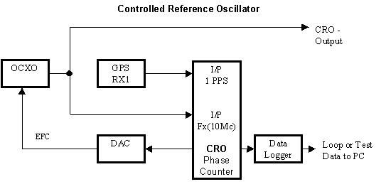
- Frequency loop for binding oscillators of all types and up to 130 MHz to a high-grade reference signal (Fig. 2) .
For these measurements, the following reference signals can be used:
- GPS, 1 PPS - Pulse
- TV, FBAS - Signal (i.e. German ZDF)
- Other references based on 1 PPS with asymmetrical pulse duty factor.
Figure 1: Simplified block diagram for oscillator measuring
Figure 2: Simplified block diagram - frequency loop
TEST PRINCIPLE
The CRO measuring method has been known of for years and was released, amongst others, in a publication of the PTB (Physikalisch Technische Bundesanstalt, Germany) in 1994 [1]. Although it primarily describes the use of the ZDF TV signal as a reference, the same measuring method can be used for the 1 PPS signal of GPS receivers and similar signals.
The test principle, as set forth in Figure 3, is based on a counter (phase counter, i.e. with 100 MHz), which counts the distance between two flanks. While the first flank opens the gate of the counter, the phase counter begins to count in 100 MHz increments. As the second flank closes the gate, the counting is halted. Was the phase counter cleared in advance, the counter would store a value equal to the time distance between two flanks in a resolution of +/- 10 ns.
In the case of the CRO, the first flank for opening the phase counter is produced with the frequency of the test oscillator. Therefore the oscillator-frequency (fx) is figured with a divider (fx -divider) down to 1 Hz. The second flank for closing the gate is either the 1 PPS signal of the GPS receiver or the VSYNC signal extracted from the FBAS signal of a TV tuner. Decisive only for the measurement is the next flank of the PPS or VSYNC signal after the opening of the gate circuit by the first flank.
For the phase counter cannot have any desired length (here 22 bit with a dynamic of 16 bit), a synchronizer takes care that the distance between two flanks does not exceed certain limits to prevent the counter from overflowing.
If the distance between two flanks never varies, the phase counter stores the same values for each measurement. Only the jitter of both flanks can produce small differences in the result, which can be safely ignored if averaged over time. So, if the phase counting value remains constant, both frequencies are the same.
Should the distance between the two flanks of measurement decrease, the phase counting value also decreases. This now means that fx has a smaller frequency than the reference-frequency.
Alternatively, if the distance between two flanks of measurement increases, the phase counting value also increases, meaning that fx now has a higher frequency than the reference frequency.
The absolute value of the phase counter in respect to one measurement is irrelevant. Only the difference of one value of the actual measurement to the value of the preceding measurement is constantly summed up and displayed. The diagram can be weighted by a statistical method, the so-called linear regression. The result is a straight-line representing the mean value of all measurements. The gradient of this straight-line represents the difference of both frequencies. It can later serve as a reset value for a proper control loop.
Figure 3: Test principle
SUBASSEMBLY AND COMPONENTS
As shown in the block diagram, the CRO consists of several subassemblies. The main two parts, the analogue and digital part, are described here. Due to a widespread offer of commercial or home brewed oscillators, which can be integrated, and in order to ease the home brew reproduction of the CRO - the oscillators, which are regulated by the CRO, were not part of this project. We thought this is an advantage for the user.
For the follow-up control of the oscillators is managed with a very small change of an analogue voltage (with the HP OCXO 10811 a voltage gain of 1 mV is equivalent to a frequency change of 1*10-11) and furthermore to avoid interference a splitting of analogue and digital-part was chosen. The digital part, with one exception, contains all digital parts of the CRO, while the analogue part, holding all analogue components, can be placed close - but spaced from the oscillator. The voltage for the analogue part can be fed by the power supply of the oscillator, thus allowing the switch-off of the digital-part while the oscillator and the analogue part continue working. A serial connection jack is responsible for the connection of the analogue and digital part.
Figure 4: CRO subassemblies
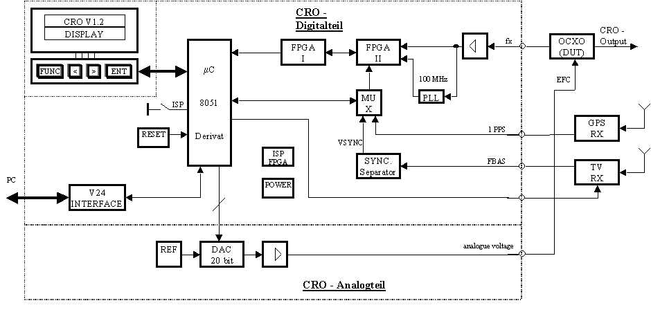
DIGITAL HARDWARE
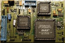
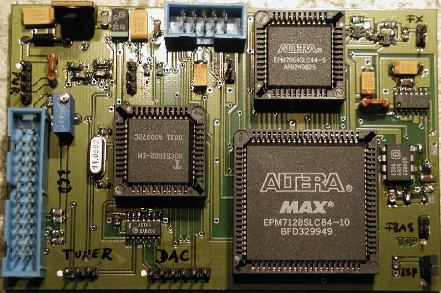
If the reference signal and the signal of the oscillator to be measured are both digitized, the rest of the measuring, the evaluation and the calculation of the reset value can also be done digitally. The peak calculation of the CRO digital platform (Fig.5) is managed by a Temic/Atmel Micro controller [2], a 8051 derivat which doesn't need a data logger and houses an 'in system' programming device. A reset-IC safeguards a prompt start after the power supply is switched on, which should lie between 7-12 volts and be stabilized by a series regulator. The connection to the outer world is realized by a RS232 series connector by Maxim [3]. For the operation a connector for a 2*16 digit long LCD-display is present. All relevant data, i.e. preset data etc., are stored in a non-volatile EE-PROM. To keep the expense on discrete component parts as low as possible, for the realization of various counters and manifold logics so called FPGA's (Field Programable Gate Arrays) were used. The memory of the FPGA's can be programmed with a free developers-software and with a home brewed programming device fed into the board. All fast logic elements were combined in a FPGA of higher quality. The slower logic is combined in a cheaper, somewhat bigger FPGA. As mentioned above, for the reference can be used either the digital 1 PPS signal of a GPS-receiver or the VSYNC-signal of a TV-receiver. The 1 PPS-signal is directly fed into the gate-logic of the phase counter, whereas the VSYNC_signal has to be derived from the FBAS-signal. For that purpose the impulse decoder from the Gennum company [5] is integrated on the CRO-board. Of course the channel switching of the TV-tuner can be done directly from the CRO. The signal of the oscillator to be measured is led through two amplifier stages to an almost TTL-level and then fed into the measuring device. A special PLL-IC by the ICST_company [6] creates from the frequency of the oscillator a further frequency of ca. 100 MHz. This frequency is used by the phase counter to measure the distance between Start/Stop flanks. This method has in comparison to DIL-oscillators the main advantage that a high precision 100 MHz-signal is at hand which is synchrone to the frequency to be measured. The absolute frequency in this respect is of minor importance for the measuring principle is based on 1s resp. 1/50 s. Drift effects of a DIL-Oscillator, however, would have a distinct effect on the result.
Due to the fact that mainly compact components are used a relative small and price worthy, double sided board could be developed. It has only two specialities - to avoid local interference special care in the layout was taken in separating the PLL-ICs from the rest of the digital part. The digital part itself fits into a standard tin-plate box. The leading out of the flatbandcables for the LCD-display and the small keyboard can easily managed by cutting the metal twice on one side (in size of the flatband) and then bending the small metal tongue for the opening. All the other inputs and outputs can be done with lead-in filters, while all HF-inputs are managed by Teflon-lead-ins.
Figure 5: CRO Digital Part
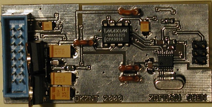
ANALOGUE PART HARDWARE
The most important analogue parts of the CRO (Fig. 6) are a 20-bit Digital-Analogue-Converter (DAC) and a high precision voltage reference. Much time was spent choosing the right DAC. Finally the so-called Delta_Sigma DAC by the Burr-Brown company [7] came out on top. It is well known for low power consumption, perfect linearity and has in addition the possibility of on-chip calibration. For a microprocessor is built in, an additional quartz is needed. A little disadvantage might be that the DAC only comes in so-called SSOP-housings, which is quite a challenge even for those who are used to SMD_soldering. The output of the DAC is fed through a low noise amplifier and than to the control input of the oscillator in order to bias his frequency electronically. This connection should be established with a very short wire. Even at normal load no voltmeter should be connected, for normal voltmeters do not have the needed resolution and furthermore unwanted interferences are caught over the connecting cables of the instrument.
The 2.5 V reference feed was found quickly. Maxim [8] offers an extreme low-noise (1.5 FVp-p), high precision (0.02%) and temperature-stabilized (1 ppm/°C) voltage-reference, which is not cheap. The highly stabilized 2.5 V are buffered low-noise und fed to the DAC. The connection to the digital part of the CRO is established by a 3-wire connection. Simple buffer stages with series resistances uncouple both circuit boards. Both voltage regulators should be high quality low-noise series regulators.
Great care was taken in the circuit design to clearly separate digital and analogue signals. Thus feedbacks from the digital part into the outgoing analogue-signal could be prevented. The circuit board again fits into a standard, tin-plate housing in which only a few lead-ins have to be built in.
It is worth mentioning again that it is feasible for the power supply to use the main transformer of the oscillator, especially if the oscillator is meant to run constantly.
Figure 6: CRO Analogue part
PC-TOOLS
For a constant monitoring of the CRO and for the control of chosen settings PC-Tools are at hand which provide all essential information of the CRO for the operator in a user-friendly format. Under normal circumstances all information are shown on the LCD-display if it is connected. However, this is not necessarily mandatory. During normal operation each second a set of important data is fed over a 232 connection-jack. If a PC is connected the LCD-display can be simulated on the computer screen as a virtual LCD-display via the program CROCON.EXE. The program CROONLINE.EXE prepares the data for a simultaneous display format, they are displayed in a graphical and a numerical form. At the same time diverse calculations are taking place, these results are displayed also. The data sets coming from the CRO are stored for documentation and later evaluation with the tool CROCON.EXE in an extra file. The data format is strictly binary, which on one side produces compact files and on the other side allows the use of other statistic tools. In addition the program CROCON.EXE is able to store all pre-settings, all other measured data and the calculated regulating characteristic. All this data can be modified and stored back into the CRO.
For the statistical evaluation of the received GPS-satellites the program GPS2.EXE is at hand. It processes the amount of visible satellites and documents how long how many satellites have been visible. From this data, conclusions about the quality of GPS as a reference for a certain location can be drawn.
The programming of the 8051 derivative is managed by the tool ISP.EXE and provide by the Temic/Amtel Company.
All tools can either be downloaded from the author's homepage or at least hints are given where they are available. A detailed reference manual of diverse programs is available as a separate file also. Furthermore construction manuals for GPS- and TV-receivers can be found on this homepage (http://www.qsl.net/dk7nt).
RESULTS
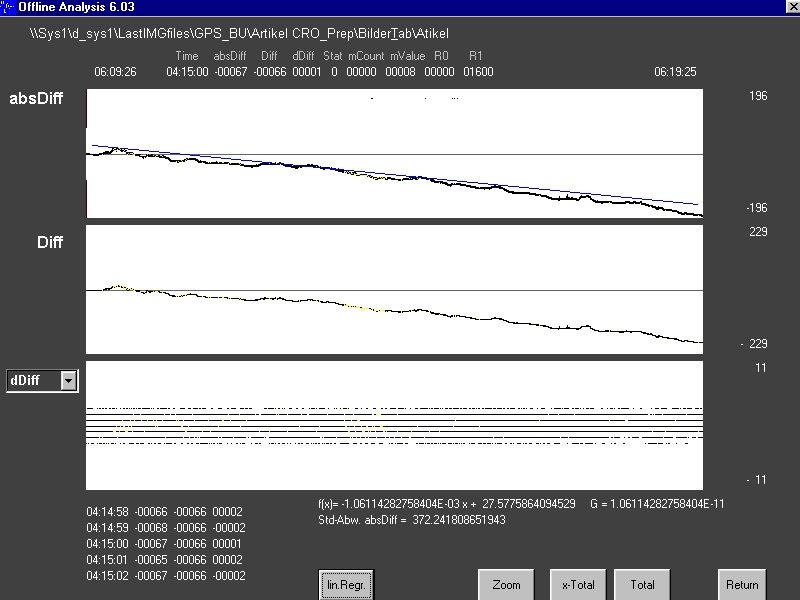
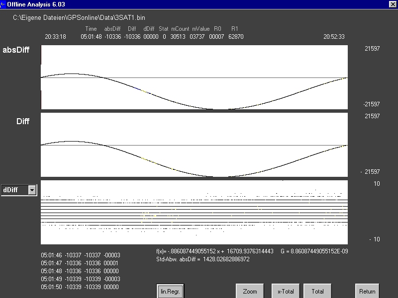
All following measurements have been made with the today usual standard frequency of 10 MHz. How the CRO functions as an accurate measuring instrument can be shown in the 24-hour measurement of a rubidium standard as shown in Fig. 7. The upper graph shows the result of the phase counting as a curve. The phase-values are stored in steps of 1 s. The inserted straight line represents the relative stability over 24 h, which is in this example -1,1*10exp-11, is statistically evaluated by linear regression. The time rate for the regression can be chosen individually within the evaluation software. In the middle the digital filtered phase-counting is displayed. The scattering is clearly visible caused, among others, by the phase-jitter during the correlation in the GPS-receiver.
Figure 7: GPS-reference versus Rb-atomic standard
For the use of the CRO the following properties of the TV-based reference of the German TV station ZDF (other TV-stations behave likewise) should be recognized. Where the FBAS-signal is not coming from a terrestrial TV-station considerable offsets occur. The deviation can reach values of 10exp-8 if the FBAS_signal is fed front end into the CRO from a satellite receiver or via cable (i.e. if the satellite signal is fed in the cable). In the case of a satellite signal the reason for the offset is that the geostationary satellite has a precession (similar to an 8) around its nominal position. The cycle of this figure is 24 hours. Subsequently a Doppler-shift follows, which directly depends on the latitude of the receiver station. The result of a satellite track line for German latitudes can be seen in Fig. 8.
Figure 8: ZDF-standard - relative satellite movement
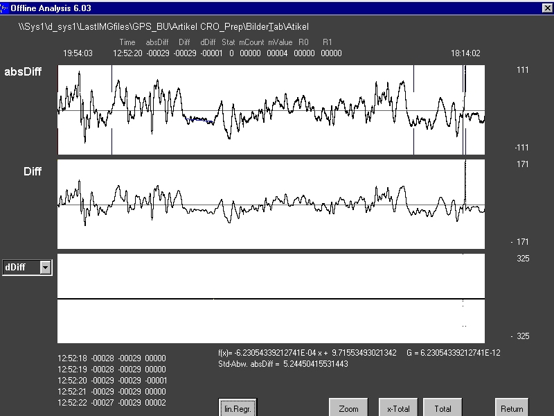
The measurement result in Figure 9 was recorded with an OCXO connected to an DCF77 (atomic time signal) over 46 h. The control loop of the receiver works with a time constant of = 2000 s. Thus, the output signal stability meets the requirement of modern commercial units, meaning, this state of the art result cannot be established with any home-brew device of maybe some earlier times. Clearly the path influences of long-wave transmission can be seen. For instance, during winter time a stable signal phase for OCXO-reset lies in the vicinity of 4.5 h (here 9.00 - 13.30 UTC), where values of 6.6*10-12 are reached. After that the maximal offset varies around 1*10exp-9 . For the quartz oscillator itself usually produces a drift in the vicinity of 10exp-10 higher useful stabilities can only be reached by integrating DCF77 and a Rubidium-standard. The stabilities in the combination of GPS and DCF77 over 24 h diverge only in the range of 10exp-12. Having in mind that the 'Physikalisch Technische Bundesanstalt' (PTB) and the National Institute of Standards and Technology (NIST) characterizes the GPS-system with 1*10exp -11 at the receiving station and that they recognize it as a trace back calibration standard, our above data have an overall high grade quality.
Figure 9: GPS-standard versus DCF77
The test possibilities with the CRO are manifold, which might be surely proven by test data of more than 30 Gbyte, which in a 14-month time period were recorded and evaluated by us. After the CRO-board was well_tried in measurement technology and the controlling software together with an optimized and drift compensated D/A transducer was finally at hand, the frequency control-loop was activated (Fig. 4). For the OCXO the type HP10811 was used. In the beginning of the measurement of the frequency control we used a second CRO-board at the output of the OCXO in order to independently record the control action and the stability. The displayed value of restsource error came to 10....5*10exp -11 and could identically be read of in the control loop as well as on the measurement device. A representative process over 9 h can be seen in the following Fig. 10, where the straight marks show the points of active adjustment. The first interval over 3 h is evaluated in Fig. 10, having a stability of - 5.6*10exp -11. This already met the standards of our project target. Impressively the second 4 h interval shows how in the first 2.5 h interval the control circuit regulates the OCXO exactly. GPS and CRO precise the measurement with a value of 3.3*10exp-12 before the drift increases to 4.4*10exp-12 enforcing another rate action. The worst values in a 10 min time interval came up to -3.3*10exp-10, this is due to interference. These unfavourable phases are displayed by the controlling software.
Figure 10: OCXO biassed by GPS
FURTHER APPLICATIONS
After finishing the works in the standard frequency range of 10 MHZ we went for the integration of an OCXO with 126 MHZ, because our second project goal culminated in the desire to synchronize master oscillators of beacons and microwave-transverters. For on one side the CRO-board accepts input frequencies up to 130 MHZ and on the other hand the fraction factor is programmable - even this experiment became a full success. Test runs with stabilities of 10exp-10 are pending. In the final stage beacons in the range of 10, 24, 47 and 76 GHZ (i.e. DBØFHR) shall be equipped with this GPS-synchronization.
COPYING
A GPS-receiver with a precise 1 PPS-output is mandatory for copying the circuit board. Good services are provided by the GPS-module MS1 OEM by the u-Blox company. A detailed description has been published in the CQ-DL magazine (7/2000) by the DARC ham radio club (www.darc.de). The title of this publication is 'Mineatur GPS-Empfänger als Signalquelle für Normalfrequenzgenerator' - and a copy can also be found on the homepage of the author at (http://www.qsl.net/dk7nt).
The copying of the CRO-subassemblies is strictly limited to private use only for ham radio operators and for their private risk. All wiring diagrams, software, even updates, can be found in the WEB under the above homepage address. However, the developing team reserves the right not to publish the software of the FPGA's. In this was we were able to build in a measure of safety in preventing third parties from participating in our patent for free. The project took us two years of troublesome developing time, spiced with hard financial input. Nevertheless, the FPGAs can be bought by the interested ham radio home brewer - they come fully programmed and copy protected.
The CRO-team is eager to find a dealer where all parts or even complete units can be purchased. At the proper time this dealer will be published under the above homepage address. Those who have not direct access to the Internet can write to the following address, sending a self-addressed envelope with a clean recordable CD:
Dipl.-Ing.Klaus Osterscheck
Marienberger Str. 29 A
D-83135 Schechen
Germany
ABSTRACT
Finally, it should be mentioned that the stability of the CRO-board can be improved by the use of high grade OCXOs, they shape up the stability by 1 to 2 decimal power. The limit for the used OCXOs lies in the region of 10exp-11 for the relative stability in the attached mode, which is Rubidium quality. All environmental and aging effects, as well as the so-called retrace problem complex of local standards, are compensated by attaching an acknowledged calibration standard.
We have endeavoured to push the optimization of the CRO-board forward. All new events in this respect can be found on the above homepage. A special thanks is due to Alexander Görich and Andreas Mangler (DD4IV) and to all the others who provided essential suggestions during realization and still support the ongoing project with great enthusiasm.
References
[1] Fernseh- und Kino-Technik 48. Jahrgang Nr. 1-2/ 1994
[2] Wireless & FC - www.atmel.com
[3] RS 232 Device, refer to [8]
[4] FPGAs - www.altera.com
[5] Pulse separator - www.genum.com
[6] PLL-IC - www.icst.com
[7] DAC - www.burr-brown.com
[8] Reference standard - www.maxim-ic.com
Information about First and Second Regression
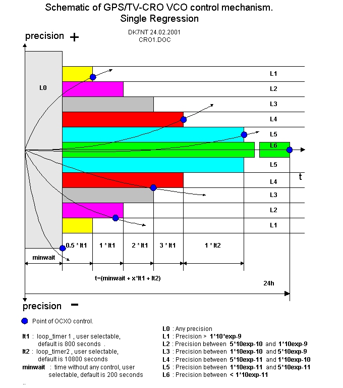 |
Diagramm: Chriteria for 1.Regression |
|
|
Diagramm: Chriteria for 2. Regression |


