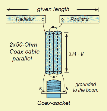
The radiation resistance is 12.5 Ohm, to
avoid losses you must work carefully and look for the construction
details.
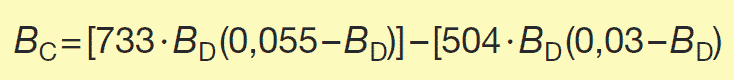
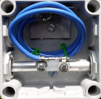
The match is made with 2xLambda/4-50-Ohm-cables in parallel. The 12,5-Ohm
radiation resistance is transformed to the 50 Ohm feedpoint with the
12,5-Ohm-DK7ZB-match.
The construction was made with "YO"
and then fine-tuned with "EZNEC". This method is working exactly,
you only have to look for the radiator length, no other correction is to
be made.
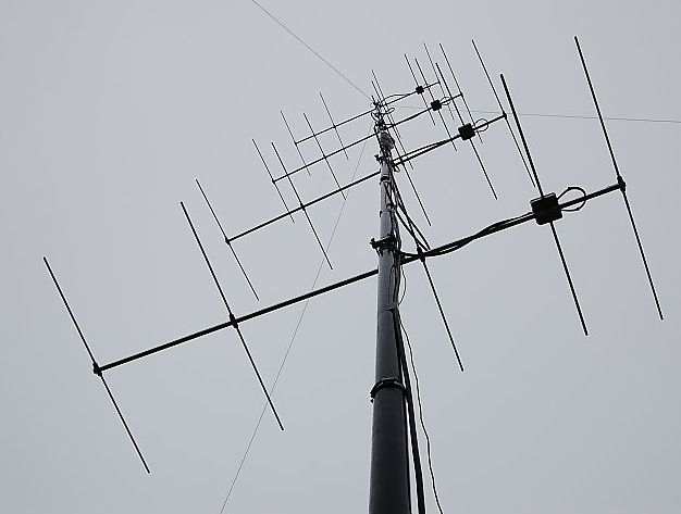
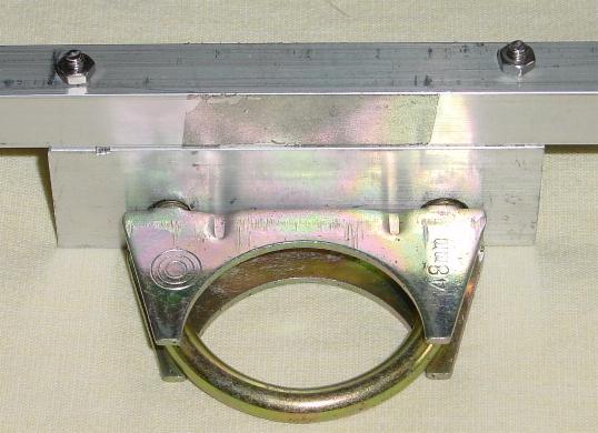
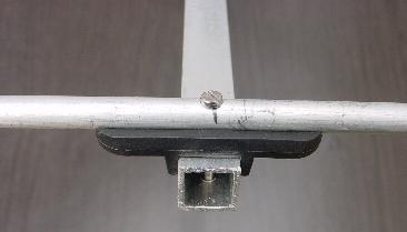
The parasitic elementes are mounted with
the insulated clamps and a 3mm-screw, the radiator consists of
10x1mm-Aluminium tubes. No other fixing is allowed because this will cause
severe detuning of the yagis! If you use homemade insulated clamps, the elements
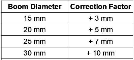
must be mounted 3-4mm above the boom. The boom is made of 15x15mm square
aluminium. The connection screw/boom (electrical "zero") has no
influence to the length of the elements, but any contact by mounting not insulated above or through the boom!
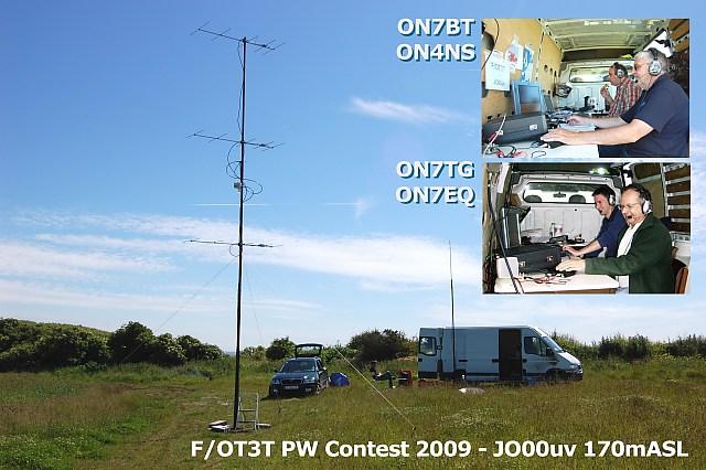
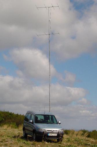
After building the antennas you should
measure the SWR, normally you must cut the tips of each side of the
radiator about 1-2mm for SWR=1.0 at 144.3MHz.
The given length of the
radiator element is from tip to tip, including 10mm spacing for the
insulated part.
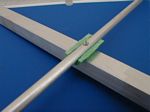
The radiator of the
2-, 3-, 4- and 5-Element- Yagis consists
of two halves with an insulated rod (8mm) in the middle part.The given length of the radiator is from tip to tip, the
insulated distance is 10-12mm in the middle part. The coax
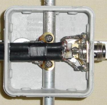
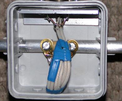
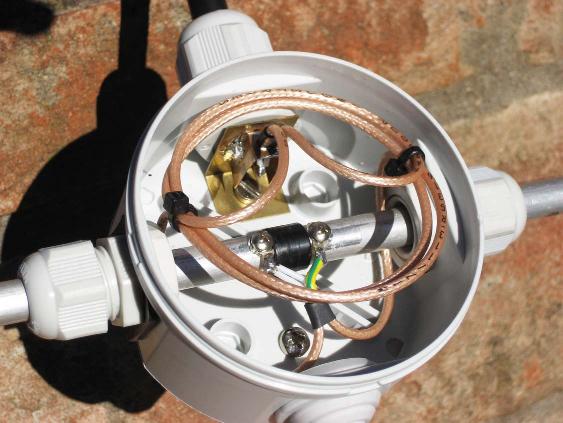
socket (BNC or better N-Type) must be grounded.
With Aircell-7 you can run 1KW to a single Yagi. Use a good quality coax (not RG-58!). The length is 42cm
(braid!) with H-155 (V=0,82), 44cm with Aircell-7 (V=0,85), with full PE-coax
V=0,67 (34,5cm), with
PTFE V=0,71 (37cm).