
 What-is NVIS Propagation?
Understanding NVIS maps
NVIS (acronym of Near Vertical Incidence, Skywave) is a special mode of propagation that allows for mid-range communication (less than 600 km), in the range between groundwave and skywave distances.
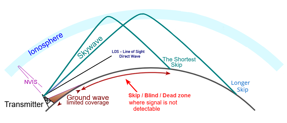
Figure 1: HF Propagation Modes
NVIS signals are vertically transmitted upwards and returned downwards by the ionosphere.

Figure 2: How NVIS provides communications within a hilly area
NVIS provides local coverage in tropical areas with a single transmitter in hilly and/or jungle areas, operating 2-4 MHz at night and 4-8 MHz during daylight.
What kind of antenna works well for NVIS?
Unlike long-distance communication methods, NVIS requires the use of a vertical radiation profile antenna.
- Dipole
- Inverted Vee
- Modification: - Adding a wire reflector
A dipole at a height of 0.1-0.25 wavelengths is an efficient NVIS antenna, maximizing vertical and nearly vertical radiation while minimizing lower-angle radiation.
The signal to noise ratio improves at very low dipole heights, due to a greater reduction in background noise and interference from distant regions.
Very low dipoles have feedpoint impedances that are 50 ohms or less. To prevent a high SWR, care should be taken to match the antenna.
Low dipoles have another benefit in that they are simple to construct.
The inverted vee is a good NVIS antenna that may even be simpler to support. A dipole suspended from a height just below the inverted vee's apex will perform almost as well as an inverted vee if the apex angle is kept at least at 120 degrees. If the included angle is sharper than about 120 degrees, the inverted vee won't function for NVIS because there won't be enough vertical radiation.
An inverted vee is frequently easier to erect than a dipole because only one support is required above ground for the center of the antenna, which must support the weight of a center insulator and feedline.
A wire placed beneath a dipole (or inverted vee) that serves as a reflector and is about 5% longer than the primary radiating element can improve its high angle radiation. When the antenna is too low to allow for that, a wire laid on the ground beneath the antenna may still be effective. The ideal height for such a wire refector is about 0.15 wavelengths below the main radiating element. However, the soil in the area affects how effective a wire reflector is.
A knife switch at the center point of the wire reflector can be used to eliminate its effect. This technique is effective for using a dipole for NVIS at extended distances. When the switch is closed, the vertical gain will increase, and the noise levels may drop.
Use foF2 map to select a frequency for NVIS operation
Watch the near real-time NVIS propagation charts showing the current critical frequency.
The highest frequency that the ionosphere will vertically reflect is foF2. This frequency is measured by ionosonde stations around the globe and used to create maps like the one below, which shows foF2 in near real-time. The following NVIS map was designed for radio amateurs:

Figure 3: foF2 map courtesy of Andrew Rodland, KC2G
The map's colored regions, bounded by Iso-Frequency contours, show the Critical Frequency (foF2) (↗) expected to bounce off the ionosphere (↗) at a nearly vertical angle. The ham bands are designated by iso-frequency contours of 1.8, 3.5, 5.3, 7, 10.1, and 14 MHz. Colored discs represent the locations of ionosonde stations. A number inside each disc denotes the value of foF2. If it exceeds 7 MHz, then 40 meters band is open. If it falls below 3 MHz, 80 meters becomes long, making local stations disappear while distant stations remain accessible.
See another NVIS map:
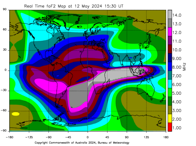
Figure 4: Online NVIS map courtesy of ASWFC
Click on this online map to view the source page. There is further information.
To plan a future schedule, use your experience what were the highest NVIS bands that could be used at different times of day, season, sunspot activity, atmospheric noise, and atmospheric absorption.
Advantages of NVIS:- NVIS covers the skip zone.
- Reliable communications; No need for infrastructure.
- Pure NVIS propagation is mostly fading-free (without QSB).
- Simple and low antena would perform very well. One person or a small group of people can quickly and easily erect a good NVIS antenna.
- NVIS can be effective in valleys and low areas.
- Low losses in the D-region, due to the shorter path to and from the reflecting E and F regions.
- Better signal-to-noise ratio compared to ground waves.
- Need lower power levels due to better signal-to-noise ratio and low path loss.
- The propagation of NVIS may be poor if at least one station lacks an NVIS-optimized antenna.
- The bandwidth is limited since only the lower HF bands from the LUF up to about 10 MHz may be appropriate for NVIS.
- Due to the variation in day and night propagation, a minimum of two different bands must be used to ensure reliable 24-hour communications.
NVIS was first used by the German Army during the late 1930s as a solution to the Skip Zone. The Allies used NVIS in the invasion of Normandy. During the Vietnam War, the US military found NVIS as a solution for communication over rugged highlands terrain. Today, NVIS communication is practiced and used by military organizations and their affiliates, as well as various members of the preparedness community, to provide reliable, fast, and secure communications with lower probability of DF location.
NVIS links- Understanding NVIS
 Rohde Schwarz
 - HF NVIS Military HF Radio
- NVIS Wikipedia
- NVIS Propagation: Near Vertical Incidence Skywave Electronics-Notes
- Near-Vertical Incidence Sky-Wave Propagation 36 pages Presentation for radio hams Gerald Schuler, DU1GS / DL3KGS
- Near Vertical Incidence Skywave (NVIS) by W8BYH, Fayette ARES
- Near Vertical incidence Skywave Propagation NVIS Antennas 80, 60, 40m bands KB9VBR Antennas
- NVIS Overview David Casler, KE0OG
- Ham Radio NVIS for Regional Communications Radio Prepper
- NVIS - Near Vertical Incidence Skywave What is it? advantages; antennas; links Jim Glover, KX0U (ex WB5UDE)
- Near Vertical Incidence Skywave (NVIS) Ham Radio School, WØSTU
- NVIS Explained - part 1 NCSCOUT
NVIS Explained - part 2
NVIS Explained - part 3
NVIS EXPLAINED citing the above 3-parts publication AmRRON - NVIS Antennas Dale Hunt, WB6BYU
- Understanding Amateur Radio NVIS Antennas and Propagation 1998-2019 Harold Melton, KV5R
- NVIS Dipole Antenna 2021 Gail Lidden, VK4ION
- NVIS antenna height 2006 Charles T "Tom" Rauch, W8JI
- NVIS - What it is and how to use it Patricia Gibbons, WA6UBE
- NVIS antenna design theory, modeling, and practical applications 2009 Ceburn Jack Swinden, W5JCK
- NVIS Army Field Manual
- Portable NVIS Loop for 80m to 40m Mark E. Cantrell, AE7TO
- NVIS Antenna (Assymetrical Inverted Vee) 2023 David T Kjellquist, WB5NHL
- A Super - Gain Antenna Project For 40 Meters 1969 Jerry Barry, K5AXN
- Radio communication via Near Vertical Incidence Skywave propagation: an overview Telecommun Syst (2017) DOI, Ben A. Witvliet, Rosa Ma Alsina-Pagès
- Analysis of the Ordinary and Extraordinary Ionospheric Modes for NVIS Digital Communications Channels Sensors (Basel)
- NVIS HF signal propagation in ionosphere using calculus of variations Geodesy and Geodynamics, Umut Sezen, Feza Arikan, Orhan Arikan
Extended Research papers
shows near-real-time indices and explains what the terms mean.
and the QRZ site since August 17, 2022,
sorted by visitors marked with their flags.
Repeat visits counted as new after 24 hours.