|
|
|
MODULE V - FUNDAMENTALS OF ELECTRONICS
Wheatstone bridge Sir Charles Wheatstone was a talented and versatile scientist. He invented the concertina, experimented with stereoscopic photography and invented the stereoscope and played an important part in the early development of telegraph communications. He didn't claim to have invented the circuit named after him, but was among the first to exploit the circuit effectively in making resistance measurements. So, what is a Wheatstone bridge? This is the circuit:
|
|
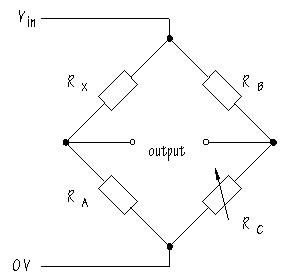
It is obvious that the circuit consists of two voltage dividers. Suppose RX is an unknown resistor value. RC is adjusted until Vout from the second voltage divider is equal to Vout from the voltage divider containing RX . When the Vout values are equal, the bridge is said to be balanced. The balance point can be detected by connecting either a voltmeter or an ammeter across the output terminals. Both sorts of meter give a zero reading when balance is achieved. In a balanced circuit, the ratio RX / RA is equal to the ratio RB / RC . Rearranging:
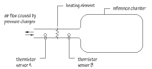
In other words, if the values of RA , RB and RC are known, it is easy to calculate RX . In Wheatstone bridge instruments, RA and RB were fixed and RC was adjusted on a sliding scale in such a way that the value of RX could be read off directly. Today, Wheatstone bridge circuits are not usually used to measure resistance values, but they are used in designing sensor circuits. A variometer is an instrument used in gliders to detect changes in air pressure due to sudden changes in altitude. The variometer alerts the glider pilot to updrafts or thermals. By circling within a thermal the pilot can gain height and keep flying for longer. One type of variometer uses thermistors to monitor pressure changes:
Altitude changes cause pressure changes which produce air flow. A heating element in the flow passage heats air which arrives at different temperatures at a thermistor sensor upstream and downstream of the heating element depending on the rate of air flow. The thermistor sensors are part of a Wheatstone bridge:
When the instrument is first set up, the preset resistor is adjusted for zero output. The advantage of the Wheatstone bridge is that only temperature differences between the two sensors will put the bridge out of balance. Cold or warm weather conditions affect both sensors equally. Air flow into or out of the reference chamber has the opposite effect on the two sensors: one will be heated by the airstream, while the other is cooled. As a result, the output changes by more than it would if there was just a single sensor device. By the way, Wheatstone bridge circuits are supposed to be difficult to understand. The circuit is usually drawn as a diamond:
It's less obvious that you should be thinking about two voltage dividers, but once you know, the action of the circuit is easy to follow. Sound sensors Another name for a sound sensor is a microphone. The diagram shows a cermet microphone:
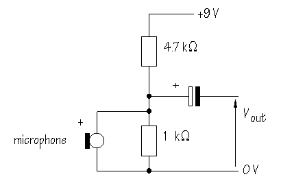
'Cermet' stands for 'ceramic' and 'metal'. A mixture of these materials is used in making the sound-sensitive part of the microphone. To make them work properly, cermet microphones need a voltage, usually around 1.5 V across them. A suitable circuit for use with a 9 V supply is:
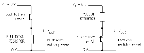
The 4.7 Signals from switches When a switch is used to provide an input to a circuit, pressing the switch usually generates a voltage signal. It is the voltage signal which triggers the circuit into action. What do you need to get the switch to generate a voltage signal? . . . You need a voltage divider. The circuit can be built in either of two ways:
The pull down resistor in the first circuit forces Vout
to become LOW except when the push button switch is operated. This circuit delivers a HIGH
voltage when the switch is pressed. A resistor value of 10 In the second circuit, the pull up resistor forces Vout to become HIGH except when the switch is operated. Pressing the switch connects Vout directly to 0 V. In other words, this circuit delivers a LOW voltage when the switch is pressed. In circuits which process logic signals, a LOW voltage is called 'logic 0' or just '0', while a HIGH voltage is called 'logic1' or '1'. These voltage divider circuits are perfect for providing input signals for logic systems. What kinds of switches could you use. One variety of push button switch is called a miniature tactile switch. These are small switches which work well with prototype board:
As you can see, the switch has four pins which are linked in pairs by internal metal strips. Pressing the button bridges the contacts and closes the switch. The extra pins are useful in designing printed circuit boards for keyboard input and also stop the switch from being moved about or bent once soldered into position. There are lots of other switches which you might want to use in a voltage divider configuration. These include magnetically-operated reed switches, tilt switches and pressure pads, all with burglar alarm applications. Conclusion Electronic circuits are built up of subsystems and are thought of in terms of INPUT, PROCESS, OUTPUT. Between the subsystems signals are transferred. These signals are almost always transferred as changing voltages. This makes it inevitable that electronic circuits include voltage dividers as an integral part of their structure. Voltage dividers aren't just a little bit important, they are fundamental to an understanding of electronic circuits. Once you have started to look for them, you will find them everywhere. |
|
|
|
Copyright �2000-2002 [email protected] -- All Rights Reserved -- Designed by WebCreations


