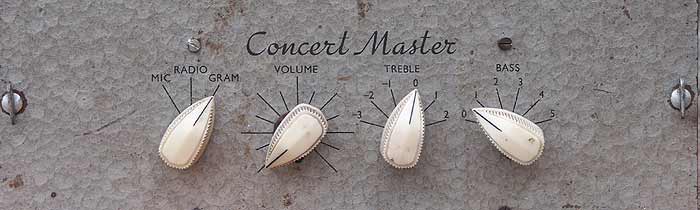
The Concert Master Valve Amplifier
Many years ago I acquired an old vintage valve amplifier, a Concert Master. Due to the need to turn everything out in order to move house it was rediscovered, and as I'm considerably older now I have far more interest in this kind of thing. Searching about on the Internet didn't turn up any reference to this amplifier, so I decided to put some information on the web in the hope that someone might stumble across it and find the information useful; this proved to be worth the while, as I have since met someone who owns another.
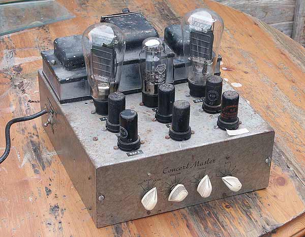
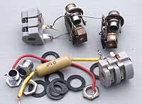
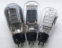
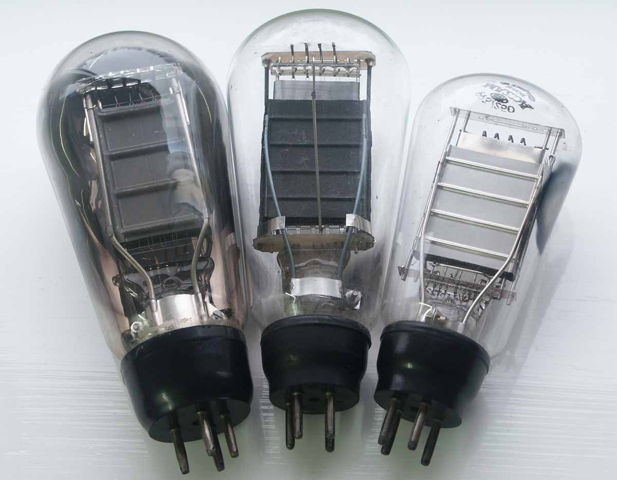
It's a typical push-pull design of the era, using a pair of Mazda's PP5/400 triodes for the output devices, equivalent to Tungstram's P27/500 which according to the chassis labelling is what were originally fitted, both being answers to M-OV's popular PX25. There are 6 smaller triodes fitted, three 6C5, a 6J5 and two 6SF5, which are high gain triodes. These six smaller valves are constructed within steel cans as can be seen in the photos, the can being connected to chassis earth to act as an effective screen. There is also a GZ32 rectifier fitted although according to the inscription next to the socket it should be the higher-powered 5U4G.
To the rear of the amplifier are the three iron-cored wound components: the speaker transformer, the mains transformer and the choke; note the chrome strips fitted around the cores to prettify things a bit. There is also a 750mA fuse fitted between the HT supply's centre tap and the chassis, although the value seems a little high and perhaps a lower rating such as 350mA would be more suitable.
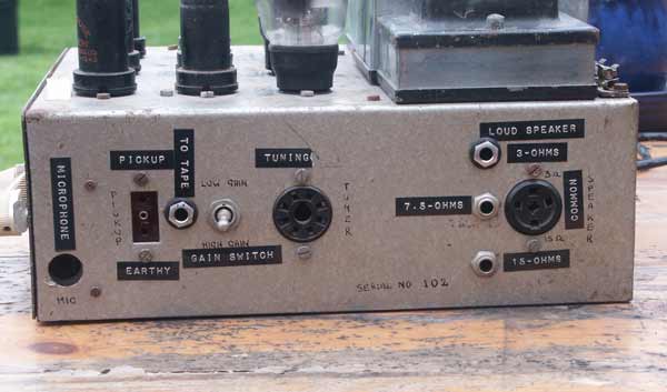
Right-hand side of the Concert Master amplifier, showing sockets
(Larger image)
The above photo shows the right-hand side of the amplifier where the inputs and outputs are located, some of the jack sockets evidently not being original. As can be seen we have the usual 3 speaker outputs to aid matching, plus some inputs and a dedicated powered socket for a separate tuner. Note also the microphone input: unusual if this was made for domestic use. I'm unsure why all that tacky 70s labelling was applied, as the sockets were adequately marked in ink anyway.
Underside of the amplifier showing removable controls section
(Larger image)
The above photo shows the underside of the amplifier with the base plate removed allowing you to see the removable box housing for the controls, enabling remote control of the amplifier. Two front latches are turned and the entire box can then be unplugged and removed, and reconnected using a longer multi-core cable using the octal socket which can be seen to the left of it. Irritatingly, I used to have this cable and the user manual, both of which have been lost in various house moves.

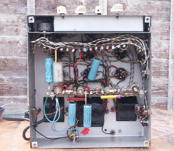
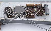
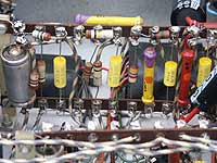
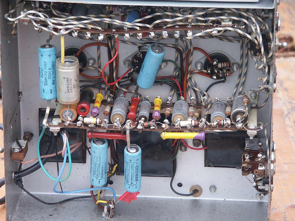
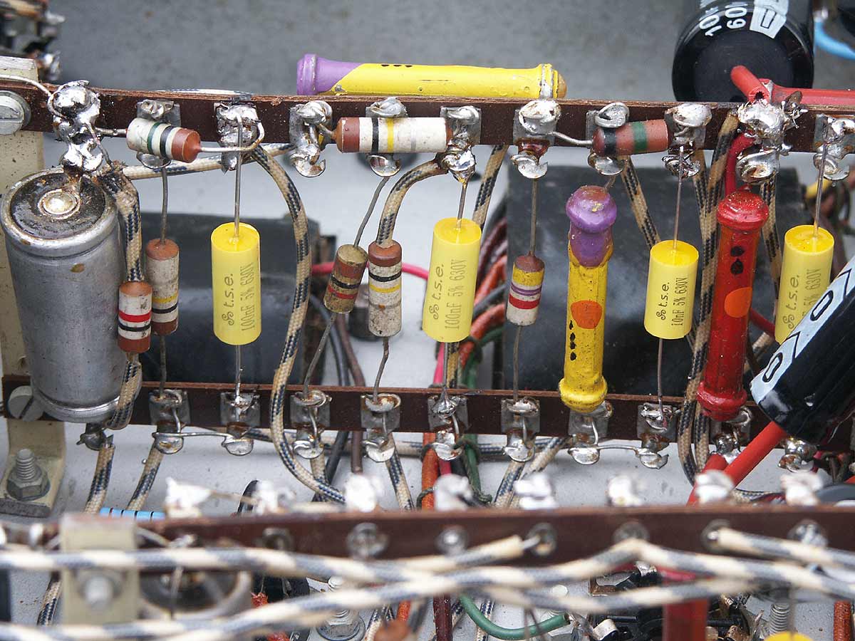
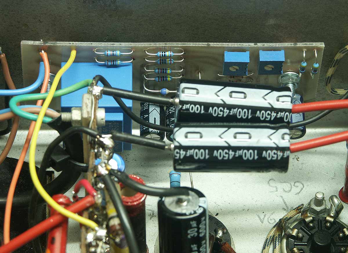
Closer view of the underside showing components
(Larger image)
The above photo shows a closer view of the components on the tag board. I believe some of the capacitors, particularly the blue 450V 8µF ones, may not be original although considering that this amplifier could be over 70 years old, this is hardly surprising. I have powered the unit up carefully using plenty of protective series resistance in the high tension supply and it does function, although 2 of the capacitors have proved to be very leaky and heat up excessively so I consider them to be unrecoverable.
The capacitors in question are in the high tension power supply and sit either side of the choke, so new ones will be fitted in these positions. The other filter capacitors in the power supply chain will also be replaced along the same lines, as it's unlikely they'll function without trouble for too long; I don't like the "recap everything" advice so often seen on the Internet these days, but in this case I agree that it's the best strategy.
Much as I'd love a totally original amplifier, modifications had already been done before I got it and I simply see this as part of the amplifier's history; electrolytic capacitors are known to have a limited life so having these replaced at some point is to be expected.
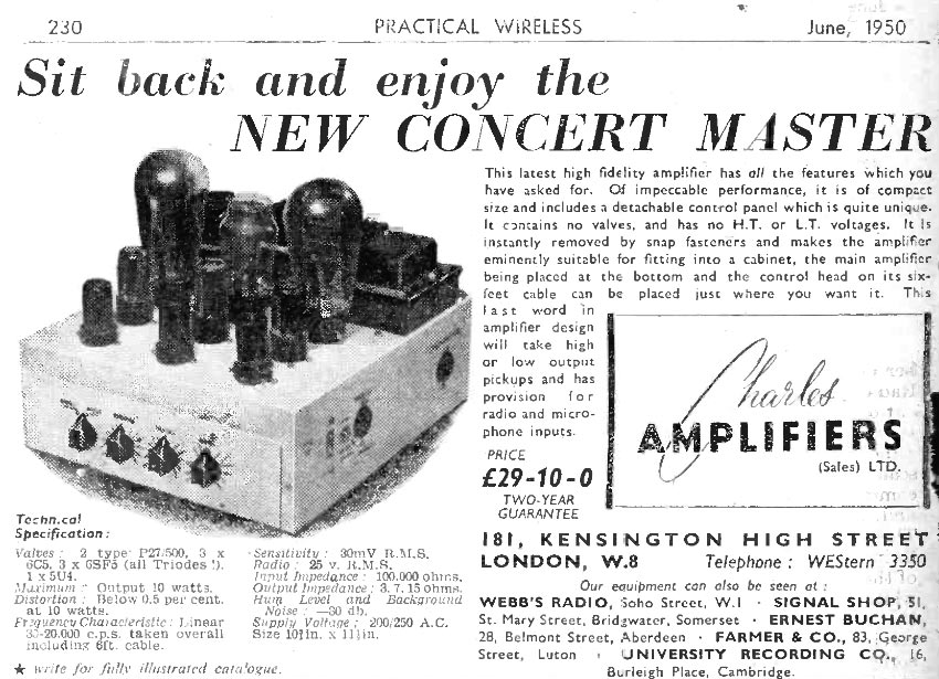
Advert for the Concert Master in Practical Wireless, June 1950
Above is an advert for the Concert Master amplifier, which appeared in the June 1950 edition of Practical Wireless. (Source: www.worldradiohistory.com) As can be seen, it was manufactured by Charles Amplifiers LTD of 181 Kensington High Street, London. The price is given as £29-10-0, which was quite a bit in the day. The version shown here appears to be a later model than the one featured on this page, confirming my suspicions that the amplifier dates from the mid-1940s.
Getting The Amplifier Working Again
Before I started any serious work on this amplifier, I was going to need some kind of schematic to work from and after much head-scratching and the consumption of several Pot Noodles, I believe I have the complete circuit traced out. I've drawn it on three pages as it's a little too big to fit clearly on one: the first three stages on the first diagram, the removable control unit on the second and the remaining stages, phase splitter and output stage on the third.
Circuit diagram 1 |

Circuit diagram 2 |
Circuit diagram 3 |
The images here are severely reduced in size and are unreadable, so click on the link in the captions to see the full-size scans of my sketches. It's always possible I've made a mistake somewhere, so if you spot anything questionable please let me know so that I can investigate it and correct things if necessary, as I'd like the information on this rare amplifier to be correct and useful to anyone else who may own one.
The bass and treble controls on the control unit seem to offer sound modifications somewhat unrelated to the positions of the switches which suggests that some of the components inside are faulty, so this is an area in need of attention, but as it's purely passive within the module itself with no DC present, this can wait.
First on the list of repairs was to replace the faulty cotton-covered 2-core rubber insulated mains lead with a modern PVC 3-core one, as the rubber insulation had perished to a dangerous degree. While doing this, I spotted two rubber grommets (mains lead inlet and 750mA fuse lead) which had gone hard and brittle, so these were replaced too.
Next was to remove all that unnecessary tacky 70s style labelling on the chassis which proceeded well with the help of some alcohol, which revealed the same details written underneath in fine ink. I see this unit has 'serial No. 102' written in ink too, suggesting at least 101 others were made.
Delving inside, I examined the various sockets which had been fitted by a previous owner in holes he had drilled in the chassis: three jack sockets for the three different speaker output impedances, and an additional socket which connected to the cathode of valve 2 via a 0·1µF capacitor which according to the labelling was to provide an output for a tape recorder. I decided to strip out all of the modifications as I saw no need for them.
The power supply electrolytic capacitors used in this unit have become leaky with two of them becoming uncomfortably hot after a few minutes' operation so I decided to replace all with new as there's a good chance of a problem occurring later if I attempt to keep any of the originals. The capacitors originally fitted were 8µF devices, but I made an executive decision and replaced most with 22µF ones, except in the decoupling filter for the early stages where I fitted some 100µF units I had in the hope of completely eliminating any traces of hum on the supply line. Extra capacitance here can only be a good thing, and places no extra stress on the rectifier.
Photos of some swapped components:
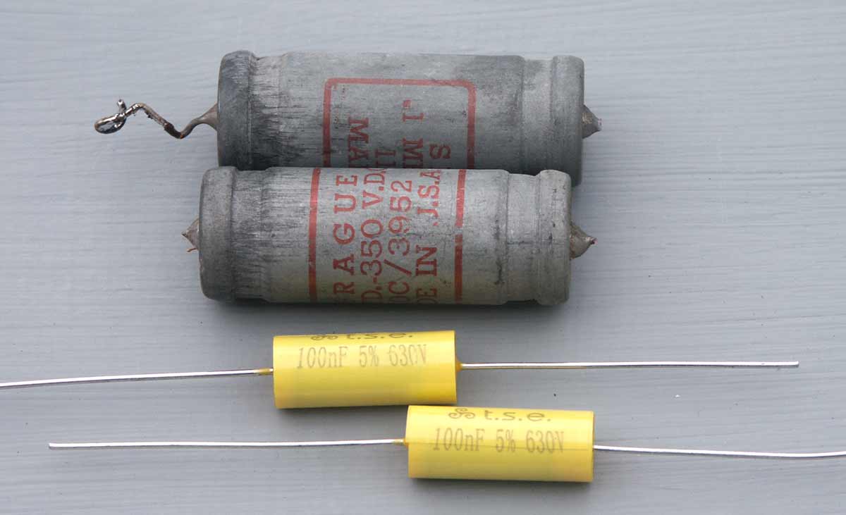
Photo showing old and new interstage coupling capacitors
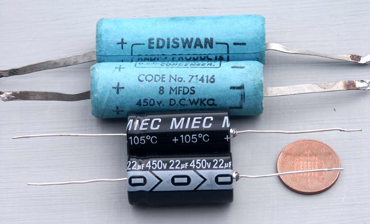
Photo showing old and new electrolytic capacitors
Once the suspect electrolytic capacitors had been replaced I was able to run the amplifier properly and start checking voltages. This confirmed that the 0·1µF capacitors connected to the grids of the output valves were leaky, causing the grid voltage of V7 to sit at almost 5 volts more positive than it was without the capacitor connected. This was quite an error so I replaced all interstage coupling capacitors (which were of the same type) with new, which allowed the grids on the various valves to sit at a more realistic level.
The eagle-eyed amongst you may notice black dots in varying numbers on the carbon rod resistors in the photo to the left: this was to make the chassis components quicker to identify by marking up certain resistors on their bodies with a code of dots, and doing the same on my working circuit diagram.
While poking about inside I happened upon a chassis earthing point that was hovering considerably above chassis potential so evidently wasn't making a good connection to the metal of the chassis. I could have spent a lot of time removing all of the many chassis connections and ensuring they made contact, but I felt my time would be better spent by simply adding wiring to connect all such points together. This additional wiring is easily removed if the desire should arise, but it does eliminate completely any chance of faults arising in the future from poor chassis earthing.

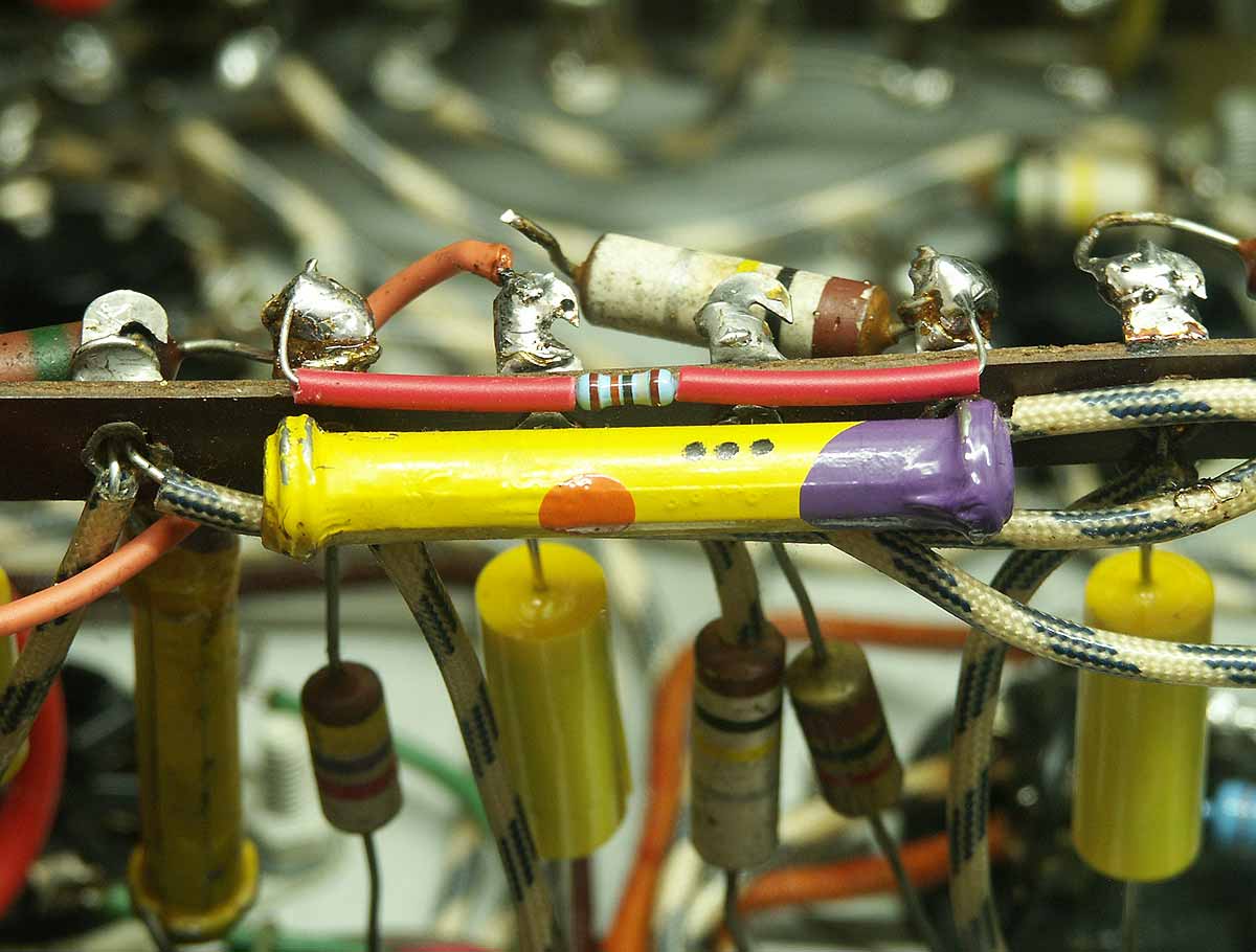
Next on my list was to deal with some of the large carbon rod 'body tip spot' type resistors, some of which are used in the power supply filtering, and some as anode loads. In all cases they have gone high by a fair amount but the worst case were the two 47KΩ resistors used in the split-load phase splitter. The phase splitter in this amplifier, as can be seen in the appropriate diagram uses a single triode with two 47KΩ resistors, one as anode load and one in the cathode circuit, with an additional 4·7KΩ resistor generating the valve's bias voltage. These two 47KΩ resistors measured 69·3KΩ in the anode load and 64·5KΩ in the cathode circuit, far higher than intended by the designer.
I was originally going to strip out the offending components and replace with new, but I do like the appearance of those old resistors so I decided to piggy-back small higher value resistors in parallel with them to bring their combined resistance within range, as I believe the old resistors have probably stabilised in value and will change little in the future. In practice, fitting a 150KΩ resistor across the anode load and a 180KΩ resistor across the cathode load brought both resistors to within 1% of the design value and would reduce imbalance in the amplitude of the two phases. (And yes, I know in the photograph that the 100KΩ resistor is disconnected at one end, but thanks anyway!)
As some of the electrolytic capacitors had already proven troublesome, I had a closer look at the cathode bias bypass capacitors fitted around V1, V3 and V4. These were all 25V 25µF electrolytics, and because of their age, were suspect. I connected a current limited supply across each one in turn and slowly turned up the voltage, noting any leakage current above that drawn by the parallel resistor. Unfortunately each one showed serious leakage of several hundred milliamps at just 10 volts, and attempts to slowly reform them didn't work so new capacitors were fitted at these points.
There was now only one original electrolytic capacitor left in this amplifier, and that was the 50V 50µF one fitted to bypass the output devices' common cathode resistor. As before, I applied voltage across it to observe any appreciable leakage current, but in this case it seemed fine. I did, however, notice that there was no current spike when making the initial connection, caused by the charging of the capacitor. Upon further investigation it appeared that the capacitor had dried out and exhibited almost no capacitance, probably due to being fitted next to the hot cathode resistor, so a suitable replacement was fitted, although technically in this design, one shouldn't be necessary.
Poor Output Stage Circuit Design
There are some examples of poor circuit design around the output stage of this amplifier which really should be addressed if the amplifier is actually going to be used, given the rarity and cost of replacement output devices, and here are my observations and suggestions.
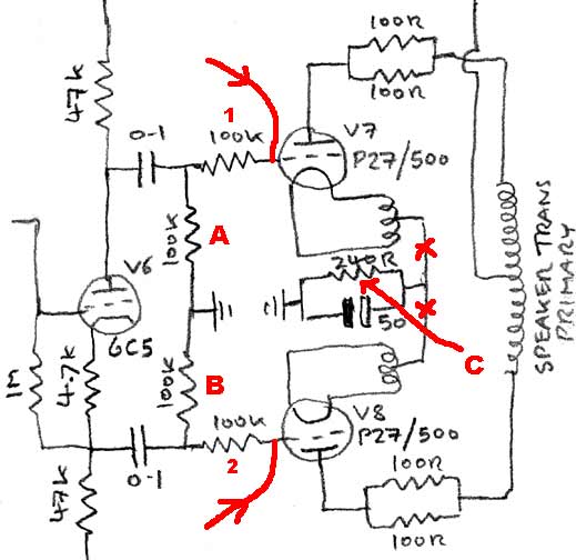
Diagram of suggested modifications
Firstly, resistors marked A & B are far too low in value, and heavily load down the output of the phase splitter, particularly the upper section which exhibits a higher source impedance. 470KΩ or even 1MΩ would be more appropriate for these grid grounding resistors.
The resistors marked 1 & 2 are far higher than necessary, as anything between 4·7KΩ and 10KΩ would be fine as a grid stopper. Having such a high value will affect the high frequency response somewhat due to the potential divider created by the grid stopper and the grid's capacitance.
The biggest offender, however, is the single cathode bias resistor, labelled C, which is common to both valves; this is very poor practice and should never be done. This creates essentially a 'long tailed pair' where if one valve has a tendency to draw a heavier current, the other valve's current is reduced, exacerbating the imbalance already there, and risking saturating the output transformer and causing one valve to run excessively hot.
As per good design and the PX25 datasheet, each cathode circuit should have its own bias resistor and bypass capacitor fitted at the points marked X on the diagram and the original resistor and capacitor shorted out (It can then be left in place to minimise disturbance). A sensible value for these cathode resistors would be something between 560R to 1k5, 5 watt wirewound, chosen separately and by experiment to give the most suitable anode current, which I suggest should be around 20mA or less for these old valves.
Finally, the red arrowed lines going to the grids shows where an external bias voltage can be injected to improve the situation if a decision is made to not change the existing bias circuitry; such an external bias unit is discussed in the next section.
Messing With The Biasing
I made some real-world measurements of the standing current being drawn by the output devices in this amplifier and was a little surprised. One valve was drawing about 35mA, meaning that at the measured 450v anode voltage it was dissipating about 16 watts, within limits although a bit on the hot side for an old valve. The other valve was drawing a massive 90mA, dissipating about 40 watts, way above its maximum rating. Unfortunately with the common cathode resistor fitted in this design little can be done to adjust individual valves. Having very finely matched output devices would probably solve this issue, but just have a peep on Ebay to see what these valves have sold for in the past, and I'm sure you'll agree that's not an option.
This potentially damaging situation needed addressing before we had a meltdown so I looked at what remedies I could dream up. I could have changed the circuit somewhat and incorporated separate cathode resistors of differing values to try to balance things up a bit, but this would have meant some major changes on the tag board, and I didn't really want to disturb the original circuitry. Another option was to build a power supply designed to inject an adjustable negative voltage onto the grids of the output devices to set the standing current at a reasonable value and this is what I ended up doing.
The power supply used a small 48v 1·5VA transformer connected to a voltage doubler which in practice gave a surprising 170v off-load. This was fed to a zener diode string via a limiting resistor to regulate the output at 128 volts, this stabilised output was then fed to 2 separate potentiometer and resistor chains to enable me to tap off an adjustable negative voltage of between roughly -20 volts and -80 volts relative to the cathodes, which was then injected into the grids via high value resistors.
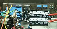
The entire supply is fairly small and was constructed on an offcut of circuit board which was mounted to the chassis using two pre-existing holes, so required no modifications at all, apart from soldering the grid bias wires in place. The device can be seen in the photo here, fitted to the side of the chassis behind the two large electrolytic capacitors, the two potentiometers for setting the bias voltage being visible.
In operation, the tacked-on grid bias supply works very well and I was able to adjust the grid voltage on each valve independently to set the standing current in each valve to a sensible 20mA or so. Getting a decent range of adjustment required disconnecting the 100KΩ resistors going to earth, as otherwise they reduced the effect of the bias injection due to loading it down. The cathode bias resistor can be left in place and acts to compensate slightly for supply voltage variations.
By far the greatest benefit of all this was that the output devices can now be run at an appropriate dissipation, meaning that when on the odd occasion that I fire up the old girl, I can be assured that those rare and expensive output valves are not being thrashed to within microns of their lives just for the sake of some background music.
With the output valves being so rare and expensive I have looked into the possibility of using something different in this position, particularly as I can now adjust the bias over a wide range to suit. I do have a pair of PP3/250 valves here which use the same heater voltage and valve base, but when I examined the specifications and saw the maximum permitted anode voltage I decided against trying them.
I also have a pair of DA30 valves, and using these is a possibility, being adequately rated for this application. I did try them briefly with the original automatic bias system but they drew such a heavy current that I quickly abandoned the idea. The DA30 requires a large negative voltage on the grid which this amplifier can't provide, although an auxiliary bias supply similar to the one I built may make using them a possibility, although I doubt the phase splitter could provide adequate voltage swing to fully drive these valves.
Hum And Noise
This dear old amplifier suffers from a couple of issues which would be considered unacceptable in these days of quiet solid-state amplifiers, namely hum and noise. The white noise is more like the sound of frying bacon than true white noise, and is no doubt in part due to those big old carbon resistors in the anode and grid circuits generating this as the electrons meander their way through the irregularities in the resistive material. It is relatively unobtrusive in use and only really audible when the amplifier is turned up on quiet passages or with no input signal at all. In any case I consider it quite quaint, and have no intention of trying to remedy it by replacing the suspect resistors as this is all part of the amplifier's character.
The hum, however, was a bit of a problem as it was quite conspicuous. One minor source of hum is direct induction into the speaker transformer from the adjacent mains transformer, but this is at a low level and difficult to cure without physically moving the transformers apart, which of course I have no intention of doing. There was another source of 100Hz hum which was at a higher level and seemed to be injected into the amplification chain after the volume control, as the position of this made no difference. Altering the bass control, however, did make a difference, suggesting that the hum was being generated around the V3 stage. It was unlikely to be due to insufficient supply filtering as otherwise this would have affected V1 and V2, which it didn't, nicely ruling that out. The most likely remaining scenario was poor layout causing power supply ripple currents to be injected into the cathode circuit of V3, so I had a look for this.
With the base plate once again removed, I examined the layout and could see that the cathode bias resistor and its associated bypass capacitor were connected to the same point as the initial reservoir capacitor's negative lead, and these to the chassis via a length of wire. It would seem that there was enough current flowing here to cause an AC voltage to appear across the wire connecting to the chassis, and this was being injected into the cathode circuit of V3 as I suspected. Isolating the bias resistor and its capacitor from this point and connecting them directly to the chassis using V3's metal can earthing tag cured the problem. There is still some very low level hum, possibly being caused by similar layout issues around other valves, but it simply isn't enough to warrant messing with the circuitry anymore, and I'm now very happy with the way this vintage amplifier works.