|
|
|
| W2WDX - The Station
in 2010 |
| Here are some images of the station as it existed, as
of 2010. |
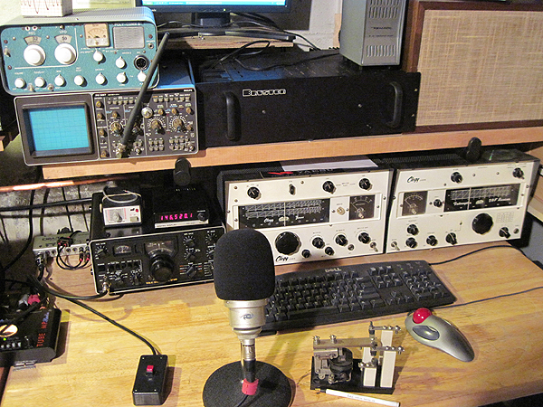
VHF Position of Station
W2WDX
as of June 2010 |
|
I had since moved several
times since my Farmingdale station. I ended up for a time in
Lindenhurst, NY and the station was sort of in a temporary state. I was
looking for more permanent digs and thinking once I find it I will build another
station to rival the Farmingdale location. Above you can see my Clegg Zeus
& Interceptor 2m & 6M AM rig. The power supply/modulator is
located under the table just below. To the leftt of that is my trusty
old Yaesu FT-221R with the YC-221 Digital Display handling SSB for
2m. Also you can see the Communication Specialists YE-64 PL
generator for it. To the left of that is an M-Audio Delta 44 box for
connecting the Soft66ADD SDR receiver, which is behind the scope. The
scope by the way is a Philips PM3267.
Additionally, there is an
ART TubeMP mic pre-amp which has recently been replaced with a Class-A
based preamp of my own design, which is RF shielded and electrically
isolated. The microphonium is an odd thing. It is a Joe Meek JM-39 large
diaphram condensor. It is very similar in sound and quality to a Neumann
TLM-103. Above the Zeus is a Bryston 4B 250w/ch audio power
amplifier. It drives the Dynaco loudspeaker to its right on one
channel (from the SDR), and the other channel is used to drive a modified
Heising set-up for HF AM applications (not shown...yet). Yes ....
That's a Polycom 6 on top of the scope, a recent restoration project for
kicks. |
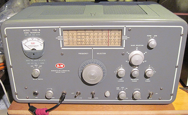
Barker & Williams 5100B HF
AM Transmitter |
| The HF AM
position consists of a B&W 5100B transmitter with the 51SB-B
SSB adapter. This transmitter is modified to put out a 20W carrier to
drive either an Alpha 8410 running two 4CX1000A tubes, or a Yaesu
FL-2100B amplifiers. They reside just above the 5100B on a shelf. The
transmitter is nearly flawless and mostly original. The only parts that
aren't are the new filter capacitors which are either CE Electronics
or Sprague ATOM types. The modifications done on this radio, while all
internal, have not changed the transmitter away from stock
performance nor caused any holes, drilling or chassis modification. All
original functions can be restored simply with original jumpers on
the stock terminal strip or switches. A fan with temp
sensor has been added for cooling, again without drilling or cutting
holes. |
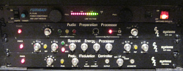
The AM Audio
Processing |
| The audio
processing for the entire station is accomplished with three broadcast
units by CRL Systems. First is an APP-400 Audio Preparation Processor.
It's essentially a compressor/limiter/gate. Next is an SEP-400A Spectral
Energy Processor which takes care of dynamic frequency control and PEP
shaping as well as audio density control. Lastly a PMC-300A which is used
to control final peak limiting, phase correction & signal
asymetry, and final output drive to the various AM transmitters.
|
| Indoors
& outdoors the entire station is wired with LMR-600 (yes, even
HF). The grounding system is a single point, low inductance system
utilizing all copper components, and all connections are made with various
widths of solid copper strap. The grounding was accomplished with six
Harger Enhanced Ground Rods equally spaced six feet apart. The ground
connection from the station, tower, and household AC consisted of 6" heavy
solid copper straps. Also an ICE Model 303 arrestor is inline with
the coax which is rated at 8kW. Incidentially, in addition to
lightning protection, my receive noise on all bands dropped substancially
after this grounding scheme was installed! Bonus! |
| The antennas
consist of an modified Windom design (OCF) fed with LMR-600 through a
custom 4:1 balun at 45' (see image below). The balun, which is rated
at 3kW continous, has two toroid coils for each leg. It has two 1:1
low permeability toroidal choke baluns cross-wired to form one 4:1 current
balun. A polymer spacer is
used to separate the individual cores which are sandwiched one on top of
the other. Each core has 10 windings of 14 gauge Thermaleze
wire inserted in Teflon tubes. It is coated with a polyimide covering
which I think is rated at a minimum of 2kv breakdown voltage. That
should give me an overall breakdown voltage at 10kv created by the
combination of Thermaleze wire and Teflon tubing. So it should be good to
about 3kw at least. As far as choking impedance it should have nearly
2000ohms on 80m and a high of nearly 5000ohms at 20m, then roll-off to
about 2500ohms at 6m. The antenna is 126' in total length with a
feed-point offset at exactly one-third. |
|
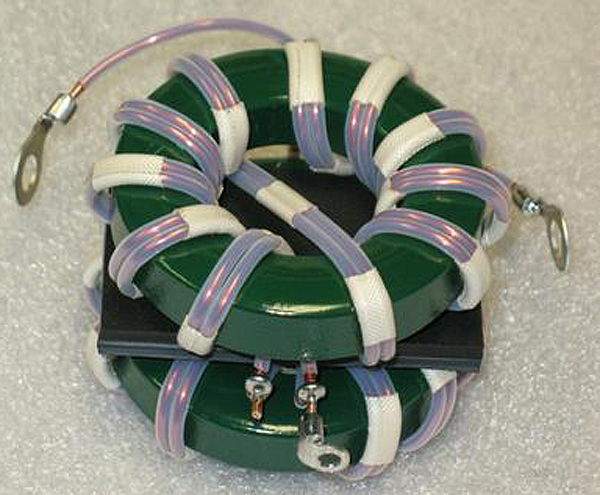
Balun Toroid Assempbly
for OCF 125'
dipole
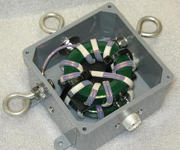
Completed
Balun Shown w/o Cover
|
|
The VHF antennas are a
combination of the OCF dipole and several horizontal loop arrays (stacks).
For 2m two homebrew horizontal loops are stacked with a spacing of
42" with the center of the stack at a height of 40'. A pair of 6m loops
are also stacked at a similar height.
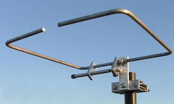
One of the 2m
Loops
The entire
antenna system is fed from the operating position to the antennas via one
single run of LMR-600. The antennas are switched using a remote switching
system at the antennas. I can switch from the OCF, to the two meter loop
array, to the 6m loop array, with the flip of a switch. The switching is
accomplished via DC injected into the coax and using the well-known
DC blocking technique.
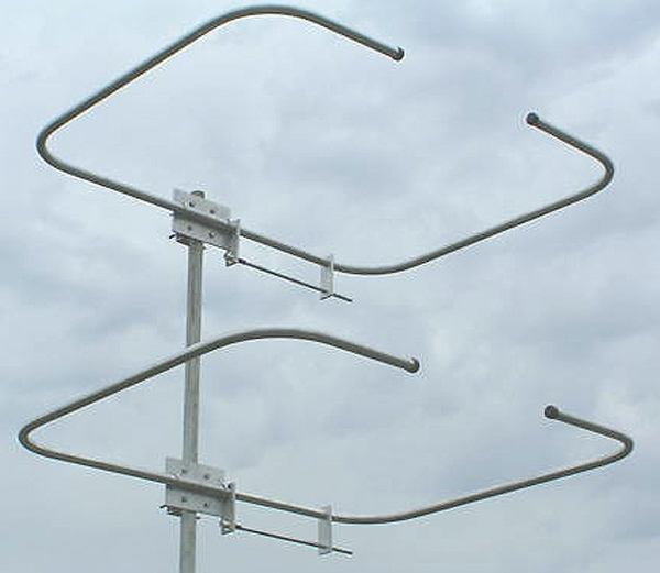
6m Loop
Stack
(Stacking spacing is much much farther in
reality)
|
| The other
equipment not shown in the images include a Murch 2000B manual HF
tuner, a Clegg Apollo 6 amplifier (375w @ 52mHz), a Commander VHF-2000
(1500w @ 52mHz), a Commander VHF-144 (1kW @ 144mHz). My old Hammarlund
HQ-100 and a Nems-Clarke 1510A are back-up receivers these
days. |
| Go to the Next Station Page |
|
|
|