| Homepage / | W2WDX Station Info / | Modes / | Other Links |
| New Additions / | QSL Info / | Amateur Articles |
First station at Viking Vintage, Scarsdale NY
as of 2012.
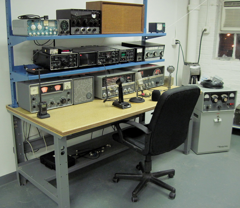
Since I was always interested in restoring vintage boatanchors (as well as other vintage electronics) I made the leap and opened a shop where I could perform restorations and resell them to other Hams. It was in Late 2010 I opened Viking Vntage. Since we were in the business of restoring boatanchors I thought it was appropriate to have a full station with some restored radios on display. The following shows this station in several forms as it developed.
The station shown in the image above was the first incarnation which went up a few weeks after we opened our doors. As you can see, we had nice collection of pristine and fully restored radios already. Since I had purchased a good number of industrial workstations for our work benches and shop tables, I decided one of these would make a very sturdy station. This is the bench you see in this image. I am very happy with the performance of these as a station table for boatanchors. They can handle thousands of pounds of weight They are also designed to accomodate electronics and have enough surface space to have very deep radios and still have enough depth for sitting, writing and using microphones. The tabletop is 36" deep. The shelving is designed to tilt down electronics and can also carry substancial weight. The entire station is constructed of steel, with a tabletop of composite wood, which is deeply varnished and hard.
The radios on the tabletop are in order from left to right: Hammarlund HQ-110AVHF Receiver with the matching loudspeaker, a Hallicrafters SX-111 Receiver and a Hallicrafters HT-37. These three radios if you looked at them appear to be brand new. They have all original surfaces, both painted and on the chassis. The chassis inside are completely corrosion free and factory shiny. Really quite nice. I was fortunate to find them in this condition. The Hammarlund and its louspeaker were new, in sealed unopend boxes, which I found at an estate sale. It was bought by someone and never used and stored away for decades unopened. I only had to remove some dried up grease, and replace the electrolytic capacitors, and align. It works so well. It even has all original Hammarlund branded tubes. This is one of those rare lucky finds I make from time to time. This HQ-110 is the full blown version with both the 6m and 2m options. Oddly, it does not have have the ubiqitous Techron clock. I have another of the same type in nearly the same condition, which sits in my living room. But this one at the shop is very special. While the HQ series are not the best performers as receivers go, I have a soft spot in my heart for them. This is because an HQ-100 was my first serious radio of my youth after I built my first cystal set as a kid.
The Hallicrafters radios are in nearly the same condition. The HT-37 was something I picked up on a lark. I have a friend who lives in New Jersey, who has a wonderful sounding station. All of his radios sound amazing on the air. He mostly operates AM. One day he mentioned he was operating on an HT-37, and it sounded as good as some of the other radios he has in his collection. Just perfect clean and natural sounding audio. I came across this HT-37 on eBay of all places and the owner was nearby so I went to take a look. It was in superb condition, very clean and corrosion free. It was also unmodified. However, the guy selling it said it didn't work quite right, which surpised me considering its condition. He went to rant about how crappy these old sideband rigs are and how good his rice box is in comparision.
Well ... I gave him the $250 he wanted and plopped it in my car. When I got back to the shop and began checking it out, it turns out the phasing type modulator was all out of alignment. Hammy Hambone and the golden screwdriver strikes again! So I put it on the bench, fired up the scopes and analyzers, pulled out the manual and gave it a good once over. Once aligned it sounded pretty good and looked good as well on the scopes. Now my Jersey friend told me about the modification he performed. So I did that the next day. And boy, what a difference it made. These radios can produce near broadcast quality audio, when aligned properly and very modestly modified, especially on AM. The fellow I bought it from was sure suprised when he heard me on the air with it a few days after I bought it. Here's a recording of me on 80m LSB recorded by a FlexRadio by the same guys who got me interested in these radios in the first place. So this recording is from the Viking Vintage station in Scarsdale NY to Central New Jersey. This is without the use of the Collins 30S-1 amplifier.
Click on the player above to hear a very strong New York Accent!
So over time I added a few more radios, sold a few and kept my eye open for more perfect examples for the shop station. Also about six months in when the Spring weather came, I began thinking about improving antennas and the stations grounding scheme. Grounding came first. I had the landlord upgrade the electrical service to my space, which was supposed to be completed before I moved in, however he was always slow to respond. After waiting seven months to have more than one 20 amp service for whole 2000sq ft space, I sent a letter from my lawyer claiming he was in breach of contract on the lease and rent would cease until the space had usable normal services. That worked, and he gave me carte blanche on what I wanted, at his expense. I ended with 300 amp three phase service with metered direct service and grounding at my panel. So I had good electrical safety ground. Now to bond that to my station grounding rod and bulkheads. Out came the heavy three inch copper straps!
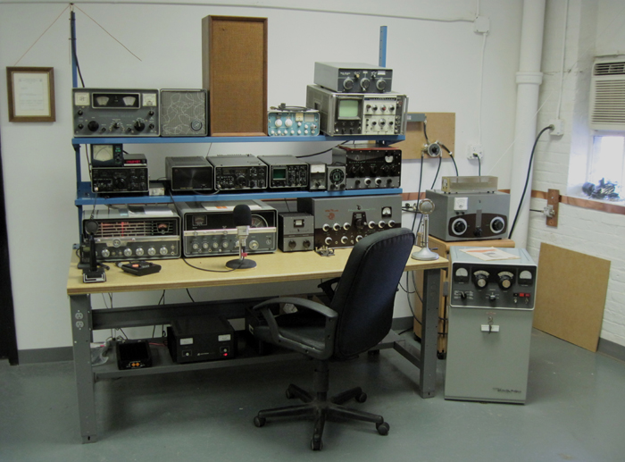
Updated Station with Grounding Going In.
As you can see a few more radios have shown up by this time. A Johnson Viking II-CDC came along to join the very pristine Viking 6n2. A new looking Johnson Kilowatt Matchbox (I was thinking about antennas, remember). Also since I was using multiple receivers I decided to use a TMC multicoupler to distribute the receiving antenna to the various receivers. This way no loss in gain would be present due to excessive loading. The receive signal for HF was derived from the receive antenna terminals coming off the back of the Johnson Kilowatt Matchbox witch also hadle all the T/R switching for the HF Double Zepp on the roof (more on that later). Sattion control was accomplished via a relay panel that allowed any transmitter to energize the antenna T/R relay in the Matchbox and also the Collins 30S-1 Amplifier. This system involved no cable swapping or switching other than coaxial switches to send whatever transmitter in use to the HF Tuner/amplifier/antenna system. To operate a particular transmitter all one had to do was flip the appropriate coaxial switch to that transmitter and key the mic. All receivers muted simultaneously when any transmitter was keyed. This way any receiver could also be used with any transmitter simply by turning up the volume. Or you could use all the receivers at once if desired.
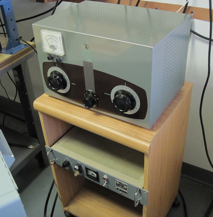
Johnson Kilowatt Matchbox and TMC Multicoupler
As you can see the copper strap was in place and was run over to the AC panel for bonding. The panel was located to the right of the window with the air conditioner. On the floor near the corner was a UFer type ground rod. This worked out to be a very good grounding point. Since all the transmission lines were to come in throught that window (once the air conditioner was moved) it was a simple matter of putting gound bulkhead just outside, and you can see the one for inside.
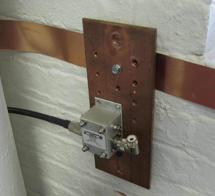
Inside Grounding Bukhead with VHF Supressor.
The grounding was then fed over to the station. There was a transition from the grounding strap to 3/4" copper tubing. The tubing allowed connection to the radios and other accesories to be accomplished easily. Eventually this coper tubing was electro-bonded to the strap for an improved connection. Use of strap of this size and using less than 10' in length from the UFer ground rod to the gear afforded a very low impendence ground. This offered a good ground at RF, as well as an improved safety grounding over the AC ground. The tranmission line grounding bulkhead ended up having a total run length to ground of just under 6 feet. While there is never 100% effective protection from lightning, this was a safe and effective grounding scheme as I could have in this location.
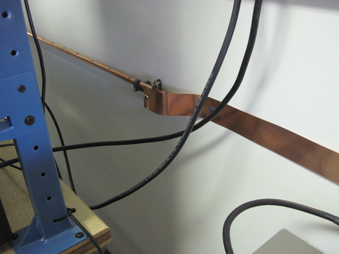
Strap to Tube Joint.
Since the Ufer ground was part of the rebar running through the walls, floor and ceiling the room had a "Faraday Cage" effect. Grounding of the individual pieces of gear was accomplished with tinned copper braid. Each was attached to the copper tubing which ran behind the table and shelves. Eventually two tubes were used running parralel to each other to accomodate more gear. All coaxial cable connections between station equipment was accomplished using Times Microwave LMR-400 exclusively.
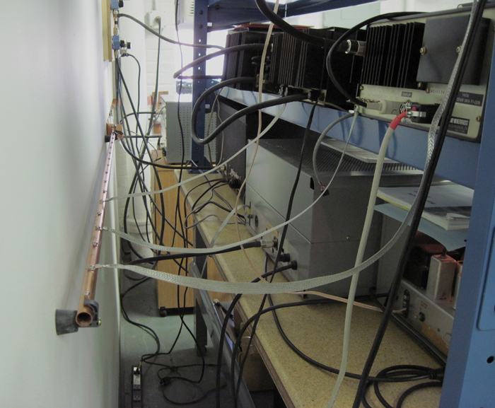
Equipment Grounding Going In Behind Table.
The station changed and evolved numerous times as far as the radio line up was concerned. Some of the radios that have come and gone (or stayed) were as follows:
- Hallicrafters HT-37
- Hallicrafters SX-111
- Hallicrafters SX-28A
- Johnson Viking
- Johnson Viking II-CDC
- Johnson 6n2
- Johnson Kilowatt Matchbox
- Hammarlund HQ-110A
- Hammarlund SP600 JX-17
- Collins 30S-1
- Collins 75A-2
- Collins 75A-3
- Collins 75A-4
- Collins 32V-3
- Collins KWS-1
- Collins R390
- Collins R390A
- National HRO-60T
- National NCX-1000
- National NCL-2000
- KLM 160W "Brick" 2m Amplifier
- Alpha 8410
- Lunar Link LA-22A
- Lunar Link LA-62A
- Gates BC-1F
- Gates M-5078
- National RBL-5
- Erco Radio Laboratories 361-TB transmitter
- Erco Radio Laboratories 362-R receiver
The antenna systems where pretty straight forward. I had decided early on to use a single doublet for multiband HF operation, 80m through 10m. This would require balanced feed-line and a good high Q link-coupled tuner. I had happened to find the Johnson Kilowatt Matchbox, which was in perfect original cosmetic and working condition. It was never modified for "transceiver use" and had all the original components in place as it came from the Johnson factory.
The doublet was mounted on the roof of the bulding. It was mounted on a long mast which itself was attached to the wall of an achtectural medieval style brick tower located at the centerline of the roof. This tower struture extended approximately 30 feet above the roof line. The mast, which was conctructed of heavy 2" aluminun tubing with additional 1.5" tubing contained inside, was tooped off with a single 4' section of the heavy walled fiberglass miltary masting. On top of this was a fiberglass horizontal 1' arm with pulley for raising and lowering the doublet center insulator with Dacron rope. This mast had a total height above the tower structure of another 40'. In total the feedpoint of the doublet antenna was located about 140' above ground level.
The length of the doublet was an odd 160' in an inverted-v configuration. It was totally in the clear with nothing near it for at least 40', which was the masting and the brick tower below. It was at least 70' above the roofline at the feed-point with the ends sloping down to about 25' above the roofline. The nearest structure or tree was well over 4 full wavelengths away and most where well below it. This happened to be one of the tallest structures in the area. This antenna tuned very easily on most of the Ham bands using the Johnson Kilowatt Matchbox. The perfromance was the best of any HF antenna I had used to date. It was constructed of the usual jacketed 14AWG stranded copper.
The doublet actually was a modified 160m G5RV made by W8AMZ, a very well constructed antenna. It was no longer a G5RV, but instead a basic balanced fed doublet. I cut off the S0-239 connection and added much more ladder-line. The radiators were also cut down to 160' total. This legth was chosen purely to accomodate the space on the roof and afford some clearance above the roofline for the sloping ends. A true random length doublet. The end insulators were reconnected and new crimp connections were created, as on the orignal design. The ends were secured to 20' lengths of large dacron rope and sercured via large eyelet lag bolts, turnbuckles and shackles at the roof edge. The antenna was tensioned fairly tightly to reduce droop. I was not concerned about stretching since it was a random length doublet, after all. (Another reason for chosing this antenna type; no stretch detuning). I particularly liked that the center insulator has hard epoxy potting compound pured into it to secure and waterproof the point where the feedline enters it. I also like the fact that the entire length of the radiator is jacketed with no breaks in the jacket from the inside of the potted center insulator all the way to end insulators. In fact the same can be said of the the entire wiring from the beginning of the feedline to the end insulators of the radiators. Fully jacketed with no breaks and no open solder connections. And all loops in the wire is secured with heavy ring-collet type crimps. A great design! Here's a image of that antenna before modification into a doublet:
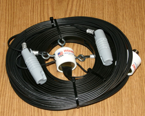
The W8AMZ 160m G5RV
before conversion to 160' doublet.
The feed-line was JSC 1313 which is a lattice type twin lead using 14AWG (19/27) copper clad steel. The nominal impedance of this cable is also an odd 370 ohms, which seemed to work well with this antenna. The length was about 130' give or take. I never experienced the change in impedance described by some when using this type of cable during rain or snow events. I also did not observe any noticable heating of the cable even at QRO AM power levels, so the match was good and losses very low. I was also very careful in its installation to make sure the phase and amplitude between each leg was in precise balance. This virtually eliminated any possibility of feedline radiation, reducing interaction with the antennas radiation pattern and polarization. It also eliminated any possible feedline radiation in the shop.
The VHF antennas where my old standby 6m and 2m loop arrays. These where mounted on the other end of the roof, on another brick tower. These where also at about a height above ground level 110'.
| Homepage / | W2WDX Station Info / | Modes / | Other Links |
| New Additions / | QSL Info / | Amateur Articles |