8 ELEMENT YAGI FOR THE FM SECTION OF 2 METRES (146-148 MHz) by Dave, VK2JDS. (October 2006)

This antenna uses a folded dipole driven element with a 4:1 coaxial balun to feed it.
Its very simple to make and has wider bandwidth than a single dipole element.

Insulating parts and aluminium are scrounged from old tv or fm aerials from your
local aerial installer, the tip or neighbours.

All elements besides the driven element are made from 5mm diameter hard drawn
aluminium wire, or they can be made from scrounged 8mm tubing from old tv
antennas etc. Even galvanised fencing wire works ok.

The pictures shown are of a modification to an existing commercial antenna I
assembled several years ago, with dimensions as listed:

Boom length is 3760 mm and it is made of 30mm diameter aluminium tubing.

Element lengths are:

reflector	955mm
director 1	850mm
director 2	840mm
director 3	840mm
director 4	835mm
director 5	830mm
director 6	820mm

Spacings between elements:

reflector to driven	420mm
driven to director 1	300mm
director 1 to 2		370mm
director 2 to 3		520mm
director 3 to 4		620mm
director 4 to 5		720mm
director 5 to 6 	720mm

Driven element dimensions:

overall length from tip to tip is 900mm to cover the segment 146 to 148 MHz
(945mm for 144.4)

The driven element is constructed from scrounged tv antenna parts comprising a
2 piece insulator section and 2 bent pieces of aluminium tubing.

The elements fold back along themselves and are cut to length then drilled
and bolted into the plastic mounting.

Note that there is a strap of aluminium joining the ends together that are
at the boom but not being connected to the feedline.

Refer to the picture of the unassembled feedpoint. The spacing between the
folded elements is 50mm.

Balun at the feedpoint dimensions:

Because the folded dipole is approximately 300 ohms impedance we need a 4:1
balanced to unbalanced transformer which is easily made from some rg213/u coaxial
cable, the same as you are using for the feedline.

Cut a piece of coax 670mm long then cut the plastic back from each end and peel
the braid out so the length of the sheilded section is 630mm.

Find or make some eyelets for the inner copper of the cable to attach to, then
solder and trim the overall length including the eyelets to be 675mm.

The centre conductor of your feedline attaches to one terminal on the driven
element as does the centre conductor of one end of the balun, the other end of
the balun has its centre conductor attached to the other terminal on the driven
element.

Join the 3 braids together as neatly as possible and then waterproof it all with
silicone etc. Note that the braids dont attach to the antenna at all.

Testing.

The antenna was mounted on a plastic mast 4 metres long and bolted vertically
polarised.

The VSWR was measured using a VHF swr meter and a 2 metre handheld connected by
about 15 metres of RG213/U cable. Results indicated zero reflected power at
146.5 MHz, rising either side of this to 1.5:1 at 145.5 and 148 MHz. Some qso's
via local repeaters indicated it has quite narrow beamwidth and easily outperforms
any vertical omnidirectional antenna.

Enjoy.
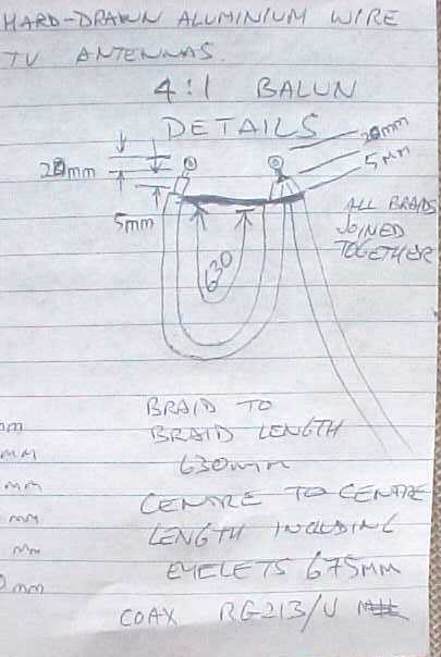
1. drawing of balun
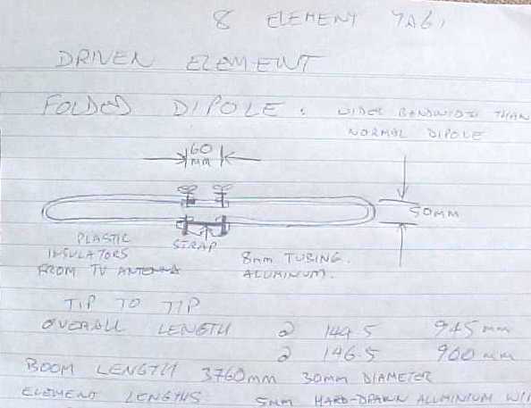
2. drawing of folded dipole
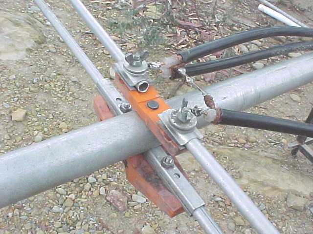
3. showing the assembled feed point
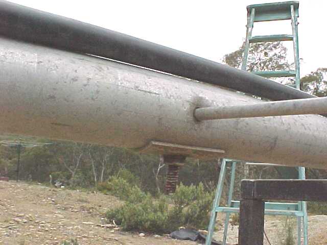
4. showing the element mounted on the boom
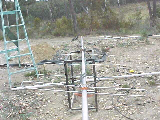
5. showing the fully assembled yagi
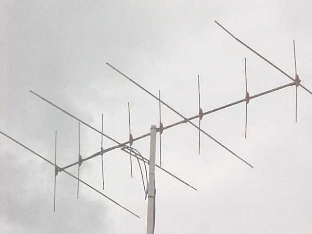
6. showing the 2metre yagi mounted vertically above the horizontal 6metre yagi