10 ELEMENTS ON A 4 METRE BOOM WITH FOLDED DIPOLE FEED by Dave, VK2JDS (October 2006)

This antenna utilises a commonly available boom length of aluminium tubing from harware
stores and allows 10 elements to be added using galvanised fencing wire or recycled tv
antenna parts.

The example in the pictures has been assembled for over 10 years using the fencing wire
and tiewire mounting technique for the directors.

Originally this antenna was part of a slot-fed phased array which was mechanically
cumbersome and difficult to rotate hence the remanufacture to make it a workable yagi.

In this experiment I decided to attempt to make a folded dipole out of straight aluminium
scraps using pliers and drills that anyone would have in their tool collection. It looks
a bit wobbly but it works briliantly and proves it can be made simply from recycled parts.


Dimensions:

Element lengths:

Reflector	980mm
Driven element	925mm overall for the  folded dipole. Refer to the folded dipole detail.
Director 1	890mm
Director 2	870MM
Director 3	870mm
Director 4	860mm
Director 5	850mm
Director 6	845mm
Director 7	845mm
Director 8	840mm

Spacings:

Reflector to driven	405mm
Driven to director 1	305mm
Director 1 to 2		300mm
Director 2 to 3		330mm
Director 3 to 4		500mm
Director 4 to 5		520mm
Director 5 to 6		520mm
Director 6 to 7		520mm
Director 7 to 8		520mm


Driven element dimensions:

overall length from tip to tip is 930mm to cover the segment 144 to 147 MHz

The driven element is constructed from scrounged tv antenna parts comprising a 2 piece
insulator section and 2 bent pieces of aluminium tubing.

The elements fold back along themselves and are cut to length then drilled and bolted
into the plastic mounting. Note that there is a strap of aluminium joining the ends
together that are at the boom but not being connected to the feedline.

Refer to the picture of the unassembled feedpoint.The spacing between the folded
elements is 50mm.

Balun at the feedpoint dimensions:

Because the folded dipole is approximately 300 ohms impedance we need a 4:1 balanced
to unbalanced transformer which is easily made from some rg213/u coaxial cable, the
same as you are using for the feedline.

Cut a piece of coax 670mm long then cut the plastic back from each end and peel the
braid out so the length of the sheilded section is 630mm.

Find or make some eyelets for the inner copper of the cable to attach to, then solder
and trim the overall length including the eyelets to be 675mm. The centre conductor of
your feedline attaches to one terminal on the driven element as does the centre
conductor of one end of the balun, the other end of the balun has its centre conductor
attached to the other terminal on the driven element.

Join the 3 braids together as neatly as possible and then waterproof it all with
silicone etc. Note that the braids dont attach to the antenna at all.
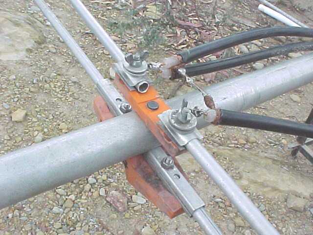
1. assembled feedpoint
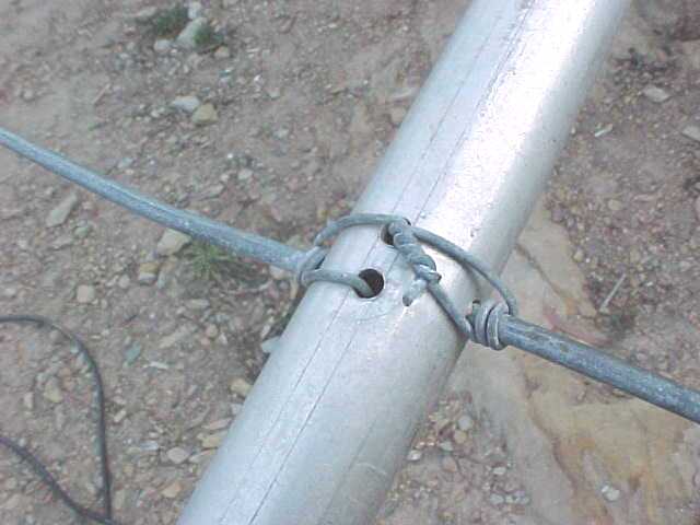
2. the directors
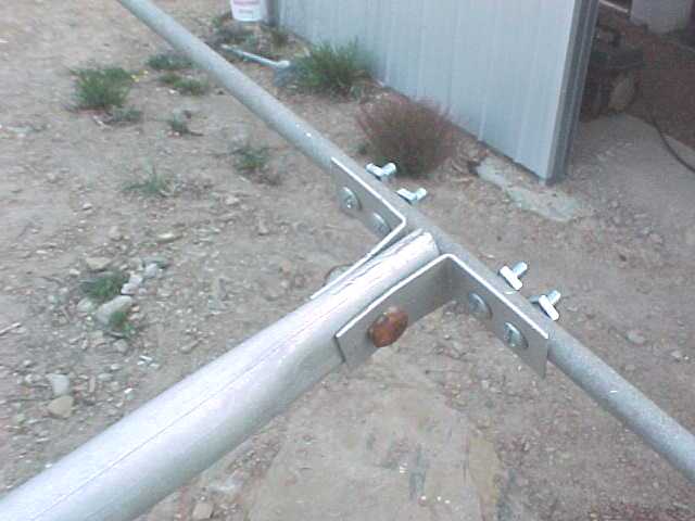
3. the reflector
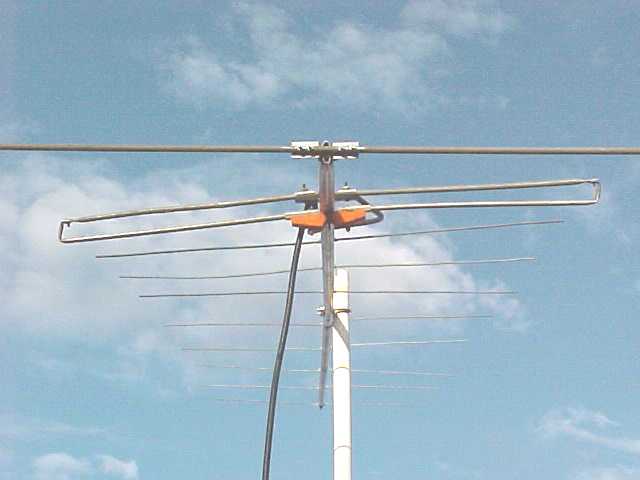
4. finished yagi up and mounted on mast