From
the Bleeding Edge Workshop
Using an ex
Pay-TV antenna for a 2401mhz
down converting
front end for sat work
Latest news! Monday 10 December 2001
Things are going well with lots of information
coming in from other hams on the connifers. Because of the way this page started
out it's format is rather upside down. there is a lot more information on
the way including Schematics LNA upgrade and some real comparisons and tests.
Please bear with me in waiting for this info to be written up. I will redo
all of the pages on the connifers into a more sensible format.

 On
December 8 at 0815utc AO40 was in the right spot for some on air trials. there
was no need to transmitt as there was an abundance of activity. The unmodified
connifer in the large Barbecue grill '27db' performed well. I have provided
a few samples of reception using the 27Db bargecue Grill. Ao40 Range to me
was 56650Km at the time .
On
December 8 at 0815utc AO40 was in the right spot for some on air trials. there
was no need to transmitt as there was an abundance of activity. The unmodified
connifer in the large Barbecue grill '27db' performed well. I have provided
a few samples of reception using the 27Db bargecue Grill. Ao40 Range to me
was 56650Km at the time .
CW was noisy but readable.
Voice complements of
WL7M in Alaska
and telemetry which
despite the noise managed to generate many blocks with good cheksums.
My helical version did not perform as well as
I had hoped despite the lower noise after installing a cap on the regulator
input. Tonight I will do the mod as mentioned below and try it in the dish.
I will also hone the design of the helical with proper matching at the feedpoint.
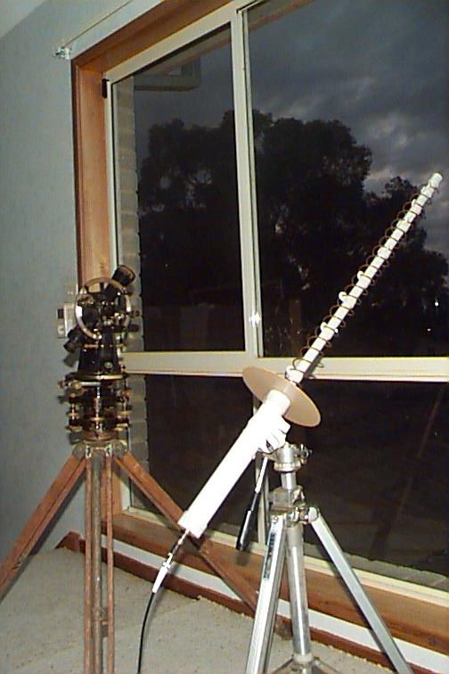
I hope you like my antique theodolite which
I have been using from the bedroom upstairs during my testing of the various
antennas.
Phase Noise Problem
A number of people have been playing with these over the last
few months. One of which is Andy VK2AES who has reported that the connifer has
excessive phase noise contributed to by the 7812 three pin regulator. A close
look reveals small smd ceramic decoupling capacitors either side of the regulator
and a 22uf electro on the output. The National Semiconductor data sheet specifes
that if the regulator is a long distance from the main filter capacitor (20Meters
of coax definitely qualifies), then a 1uf Tantalum should be placed between
ground and the input to the regulator. The cap should be as close as possible
to the regulator. Andy has done this mod and reports a dramatic improvement.
I now have a sweeper that covers .1 to 12Ghz it's time
to check the usable frequency of these as well as the Pacific
Monolithics downconverters. If need be the removal of the Ceramic filter
block's will be lookeed into also.
Some measurements have been made and can be seen here.
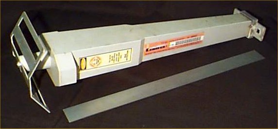
This is the Preamp/Downconverter with an internal dipole that
mounts in the middle of the reflector a picture of it assembled and on a dual
axis rotor can be seen here.
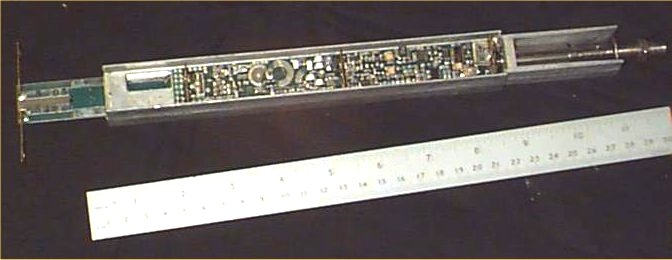
This is what's inside. Two SMD PCB's back to back in a shielded
case. at the end is a center fed dipole made with flat copper strips.
This antenna was used to recieve pay TV from black mountain
tower in the 2.4Ghz band my rough measurements show 2401Mhz being down
converted to 450Mhz. The internal oscillator crystal is labeled 7.6210Mhz
. Here's where the guessing starts untill further accurate measurements
can be made. 2401Mhz in minus the downconverted frequency leaves us with
1951Mhz when this is divided by 256 'ie: an 8 bit counter in a PLL loop'
it gives us 7.62109Mhz. That's damn close to the number on the crystal.A
bit of probing shows the crystal running at 7.6212Mhz. A nearby IC has
22.864mhz and 15.243mhz . 1951Mhz divided by 128 'ie:7 bit counter equals
15.24218Mhz Hmmm! that sounds close to what I measured on that chip. half
that comes to 7.6215Mhz.
Looks like we can start fiddling with that crystal now
and see if we can move the down convert frequency into the ham band !!
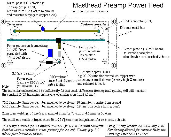
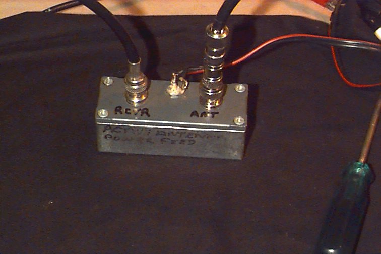
The antenna takes DC power from the coax, Positive to
the center drawing around 300ma. They have a 12 volt 3 pin regulator (7812)
in them which requires a minimum of 2 volts differential in order to regulate.
A surplus of between 3 and 6 volts would be fine. 18Volts positive on the
center of the coax provided by a masthead power feed box is what's
needed in order to get around any cable losses in long run's. Peter Ellis
'VK1KEP' has drafted up one that I have made. I't details are here.
For a look at it heres an image.
This unit is designed for 75 ohm coax so you may want
to make a 1/4
wave coaxial transformer at the reciever end to bring it's impedance
down to 50 ohm, If you feel the need they are a little tricky to make and
not that essential for recieving only.
These unit's are more commonly 18db gain however some have a
larger dish of identical construction wich have a gain of 27db. The photo on
my Dual Axis Rotator page shows an 18db version. There should be nothing to
stop us putting the downconverter with any reflector we like. Mabey later!
Things that we will be trying soon.
1. To alter the crystal ferquency in order
to bring it's output down into the 70cm band. This seems like a good idea
but it could be a problem if you want to listen to your transmissions through
the satellite. That is if the up link is 70cm in the case of AO40. I will be
sticking to the un modified antenna as I have a Win-Radio and a Yaesu FRG9600
which both are controlled by the computer and work happily at 450Mhz. Andy VK2AES
has ordered some crystals and should have one operating In-Band soon!
2. Placing the antenna in a more complete
dish to improve gain. This definitely sounds like a good thing to try. The larger
barbecue grill (27Db) is perfect but they are not as common.
3. A multi gang approach may work. It also
provides an easy way to get the impedance down to 50ohms. ie:using a simple
phasing harness as described in the ARRL handbook etc.. The big question is-
Are they all simmilar enough in their gain/phase properties and down convert
frequency to make this possible? I don't think so. It may be possible
to feed the 7.6215 crystal from one to drive the others. This sounds like trouble
to me, I think I'll try the large dish approach first.
4. Constructing a Helical antenna to feed into the down-converter
seems straightfoward enough. Here's my attempt at a helical
antenna using the connifer
Credit goes to Peter Ellis 'VK1KEP' for coming up with
the idea of using the connifer antenna for sat work. Thanks Peter. Also
Thanks to Andy VK2AES and Carl VK2TP, These guys have real test equipment and
are cool with the black art of UHF electronics.

This Information is provided by Kerry Richens VK1TKR in
the pursuit of Amaetur Radio and the free exchange of knowledge and ideas.