From the
Bleeding Edge Workshop
A Connifer
2401mhz down-converting
front end behind a Helical antenna
When I started on the idea of designing a helical
antenna I browsed the web for an easy to use helical design program. There
are a number of speradsheets and programs to do the task but I found a number
of discrepancies in the results. At this point I would like to point out that
that I am only drawing from other peoples work and web documentation. It seems
that a number of formulas regarding helical design have been incorrectly interpreted
due to subscripted variables in equations being seen as actual operators (eg:
'C subscript a' seen as C/a). I have written a program that I believe to be
correct to caluculate helical parameters and allows for shortening of the
effective wavelength due to effective velocity factor when the helical is
wound on a former.
It seems that the only saving grace in all of
this is that the helical antenna is a naturally high bandwidth beast and as
such does not really matter much what you do as long as you stick to some
basic rules about pitch and diameter to ensure that it operates in the axial
(endfire) mode with a major lobe in the middle. An often unmentioned mode
is the conical mode which occurs then the diameter is too great or if the
pitch is too low.
My program is in my opinion the good oil because
it is real easy to use and makes experimenting with variables extremely easy.
No Punch Card Programming techniques here. The idea is that if the required
variables ae there the results will also be there.
So, Download Kerry's Helical
Design Program.

Here is the finnished product ready for mounting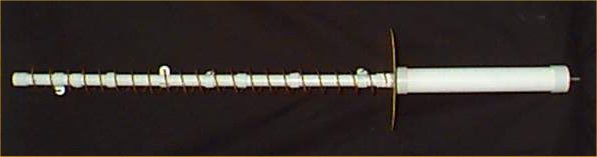
This is the insides of the downconverter module showing the internal
dipole that mounts in the middle of the reflector a picture of it in original
form assembled and on a dual axis
rotor can be seen here.
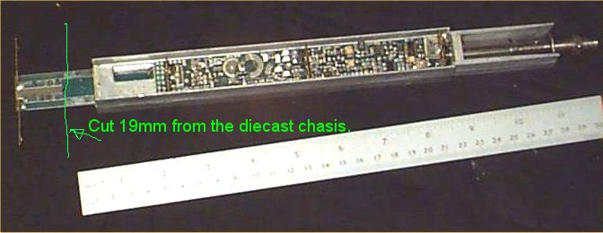
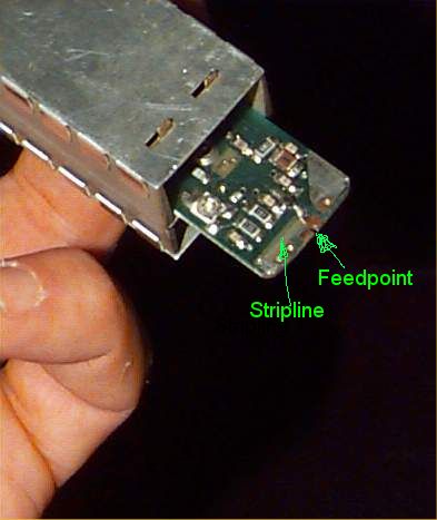
After Removing the electronics from it's case the dipole and
the1/4 wave stripline Balun need to be cut off this leaves 19mm of pcb protruding
from the diecast chasis. on one side of the PCB is the groundplane and the other
the feedpoint in the center which has a stripline inductor? going to the groundplane
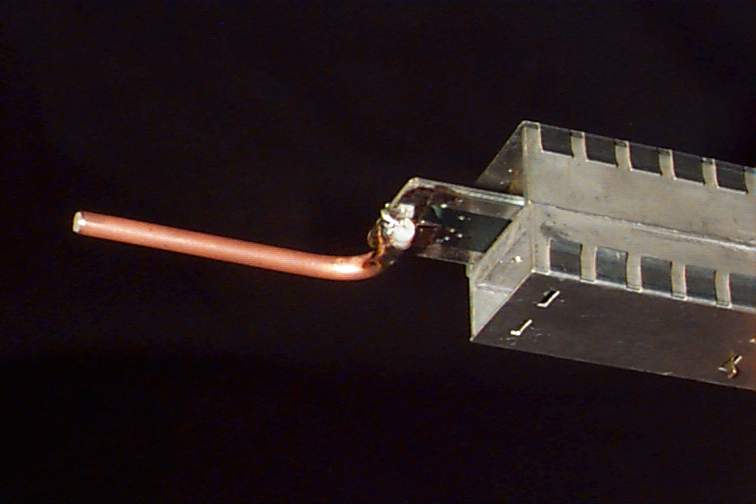
The hardline coax is bent in a tight but not kinked
right angle curve and soldered to the groundplane. leave about 2 to 3 mm of
dielectric and bend the center conductor at a right angle then over the board
at the center. Solder on to the feed point. The end that protrudes needs to
be right beside the inside surface of the conduit so that it clears the 20mm
conduit nut. Make the coax long enough to protrude 45mm from the PCB. once the
hole is drilled through the groundplane and endcap assemble the unit. Cut the
coax allowing for 5mm of outer sheath protruding and 3mm of dielectric. Leave
the remaining inner core from there.
The parts shown here are a Copper or PCB Disk 90mm Radius,
a piece of 40mm ID water Conduit 305mm long, 1X 40mm end cap with a 10mm hole
and one with a 20mm hole so suit the threaded conduit terminator. These parts
form the housing for the converter. The second image
is the conduit terminator that holds the 20mm OD electrical conuit. It sandwiches
the groundplane between itself and the 40mm end cap as shown below.
This shows both sides of the groundplane and
associated bits. The right photo shows the Hardline coax protruding enough for
it's sheath to be soldered to the groundplane.
Here is the first part of the assembly done excluding sealing
and feeding a small hardline coax through the endcap and groundplane. In my
opinion the end with the output connector should be glued with an apropriate
conduit glue and the other end should be sealed with a caulking compound, including
both sides of the Groundplane surface.

A standard 20mm conduit saddle with one end cut off forms the
supports for the helical. It has been heated with a hot air gun to curve it
around so that it firmly clips onto the 20mm support conduit. The saddle clamp
hole ends up at a 20mm radius which in my opinion is perfect for 2401Mhz.

The real tricky bit is winding the spiral so that
it ends up at exactly 40mm diameter. There theoretically should be a matching
strip between the coax and the spiral but were not transmitting and it seems
to work ok. "Not very High-Tech but it gives scope for improvement"
NOW!! Get my helical
program freeware and see what you can do !

This Information is provided by Kerry Richens VK1TKR in
the pursuit of Amaetur Radio and the free exchange of knowledge and ideas.