Armed with an e-mail from Graham Wiseman and a PM downconverter
I went to work.
Here's what Graham had to say.
Hello Kerry
After cutting the thing open, it
became obvious that the connector screws into a threaded section of the
mount/heatsink, and that there was a pin
soldered to the board that connects
to the Type F Through-Connector inner. I clamped the connector in a strong
pair of pliers using some rubber to
protect the thread, and simply
unscrewed it. (Leather would probably have been better).
It seems obvious that this method
is the best dis-assembly method instead of cutting the tube open as I did.
The mounting screw nearest the antenna also
needs to be unscrewed. When these
are unscrewed, the plastic housing (the actual unit) should simply slide
out of the metal tube.
Dis-assembly of the plastic housing
is a different matter, I tried the methods I normally try, with limited
success. I ended up slitting it with a sharp knife, taking
care not to damage any internal
components (there is no internal metal box for protection). Another factor
is the increased brittleness caused by the UV exposure.
When dis-assembled, a pair of PCBs are revealled, appearing to be one for the vco/synthesizer, one for the RF/Mixer (which extends to form the printed antenna).
There are two small sheet metal
shields, one on each side of the board. Under the one on the RF side of
the board is a printed stripline filter. If this is in the RF
path, it could probably be cut
down to raise the operating frequency to the 13cM satellite bands. Hope
this information will be of assistance.
Regards, Graham.
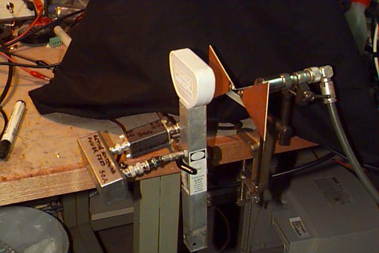
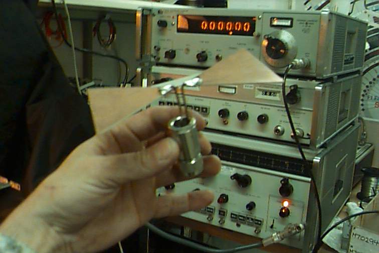
This is a photo of the unit in a Dodgy-Brothers test rig.
It is plugged into a power feed box and then directly fed to an RF
Detector. The RF Detector drives the vertical axis of a cro and the sweep
signal from the microwave sweep generator drives the horizontal axis. The
funny antenna is a crude but effective broadband
Bowtie Antenna connected directly to the sweeper output.

After Removing the unit from the tube I Split the case
using a new stanley knife blade. I rested the unit on a vice and
then placed the blade along the seam. With a small tack hammer I hit the
top of the blade quite firmly. Move around the seam untill it opens.
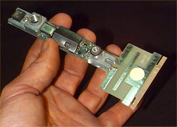
You can see the threaded hole at the top where the connector screws in at the other end is a center fed dipole with some passive reflector elements. Maximum radiation is in the direction of the Grill that this thing mounts in. It has a 7808 Regulator chip so it should run on 11 volts up.
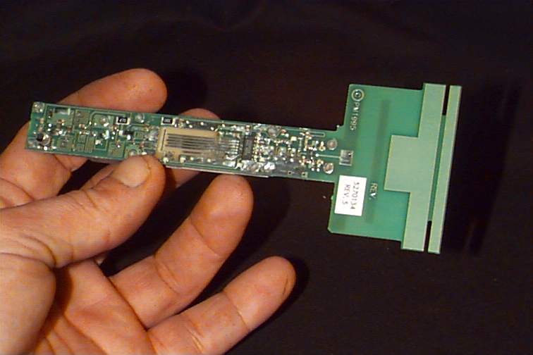
Here you can see what Graham identified as a Microstrip
filter section right in the middle. Sounds tricky retuning this. Mabey
if I had about ten spare ones to play with :) Worth a try though.
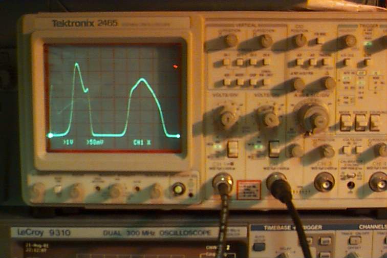
This sweep shows two bands just as found with the connifer.
There are no gain details as evereything here is an indication not a measurement
I will provide estimates of bandwidth in the next day or so. The critical
factor is that the dropoff of the upper band is right on 2401Mhz. It's
hard to do real measurements without real test gear. but my impression
from what I have done is that it will just scrape it in with reasonable
gain.
![]()
This Information is provided by Kerry Richens VK1TKR in the pursuit of Amaetur Radio and the free exchange of knowledge and ideas.