VE3EG/VE3HHT
The Amateur Radio Website of Keith Thomson
Voltage Monitor
My White Box 10 GHz transverter is unstable from time to time in contests, so some troubleshooting and improvements are required. I set up a battery so that I can run the local oscillator in the car on the way to the operating site. This has really improved the warm-up drift on site, but the occasional instability remains a problem. The two obvious culprits are the local oscillator and the power supply. Since the local oscillator alarm LED does not light during the periods of instability, the first and easiest thing to check is the power supply.
The 20VDC required by the White Box local oscillator is created by a 12V DC/DC converter whose output is connected in series with the battery. The resultant voltage is regulated to 20V by the original White Box linear regulator circuit. If either the DC/DC converter or the regulator is faulty, the 20V output could drop, causing the oscillator to become unstable.
I built a small voltage monitor circuit and connected it to monitor the 20V supply to the local oscillator. The LED on the voltage monitor lights if the monitored voltage is above approximately 19.2V, indicating that the power supply is operating more-or-less correctly. See Figure 1, which shows the voltage monitor mounted above the top of the local oscillator compartment of the White Box.
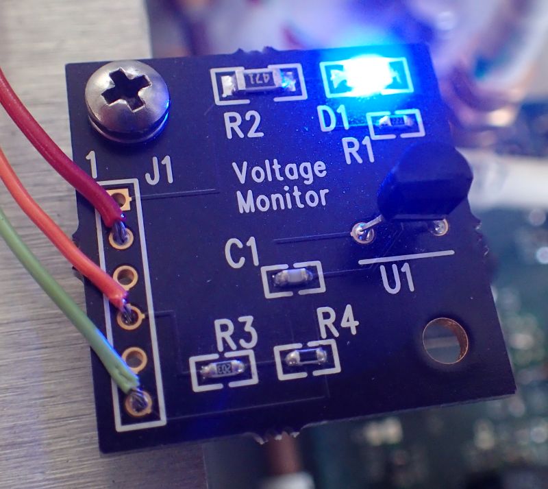
Figure 1. The Voltage Monitor installed on the White Box
The schematic of the board is shown in Figure 2. The voltage is monitored by a TL431 shunt regulator, which is used as a comparator in this circuit. The circuit is powered by the white box battery voltage (nominally 12V), and R1 ensures that the TL431 has enough bias current to operate when the LED is off. The resistive divider formed by R3 and R4 presents a fraction of the 20V supply to the input of the TL431. The TL431 will turn on, lighting LED D1, if this voltage exceeds its internal reference voltage. Resistor R2 sets the current through the LED. Capacitor C1 bypasses the voltage at the input of the TL431 to remove any RF signals induced on the wiring, which helps prevent false triggering.
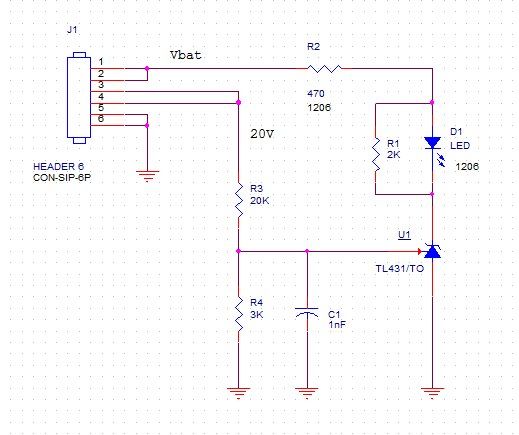
Figure 2. Schematic Diagram of the Voltage Monitor.
The parts list for the voltage monitor is shown in Figure 3.
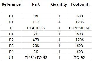
Figure 3. The Voltage Monitor Parts List
If you would like to build your own voltage monitor, the project is shared on Osh Park. Blank PC boards can be ordered for "TL431 Voltage Monitor", shared project kAhWnDhV.
To calculate the values of R3 and R4 for your monitored voltage, refer to the datasheet for the TL431, which can be found on the Texas Instruments TL431 webpage All parts on the board except the TL431 and the connector are surface mount. The pins on input connector J1 are spaced at 0.1 inch but the holes are drilled to 0.035 inch, so standard headers with 0.025 inch square pins will not fit without some rework.
Unfortunately, although the voltage monitor always showed the power supply to be working properly, the White Box remained intermittently unstable.
Copyright Keith Thomson, 2018.