VE3EG/VE3HHT
The Amateur Radio Website of Keith Thomson
White Box Local Oscillator
My White Box 10 GHz transverter (see my White Box page) came modified for high-side injection with an intermediate frequency (I.F.) of 145.1 MHz. In high-side injection, the local oscillator (L.O.) signal is higher than the intended receive frequency. Two advantages of this scheme for high-side injection are:
- little work is required to tune the White Box L.O. for operation at these frequencies.
- since many 10 GHz operators use low-side injection at an I.F. of 144.1 MHz your I.F. transceiver is usually operating at a different frequency than other operators at the same location. This can lead to less interference.
Two disadvantages of high-side injection are:
- you must use the opposite sideband (LSB for high-side injection on 10 GHz) so signals sound reversed to those, like me, who are used to USB operation on VHF and UHF.
- tuning is reversed (tune upwards to go downwards).
Neither disadvantage is much of a problem, but they do add to the challenge for a rookie 10 GHz op. A further disadvantage relates to the FT-817 that I use as an IF transceiver. Using high-side injection means that you must use LSB and CW-R modes. When switching between these modes, the FT-817 changes frequency which requires you to re-tune. One more challenge!
After my first season of 10 GHz operation, where I found I had enough to do to keep up, I was able to purchase a crystal that would allow my White Box to operate with low-side injection. I would be willing to live with the possibility of interference in order to have tuning work properly.
From what I have heard, some White Boxes tune easily to low-side injection and some don't. I did not finish the tuning process but it was an excellent learning experience. Although White Boxes have been available to hams for a long time, I have found relatively little information available on the VCO and multiplier section of the L.O. so I am describing the circuitry and the process here to help others who might want to change their White Boxes to low-side injection.
I learned a lot about the L.O. operation from The Complete X-Band Portable Transceiver.pdf on the website of Dave Glawson, WA6CGR, the White Box modification page of Peter Day, G3PHO, and the White Box modification paper by Steve, VE3SMA and Murray, VE3NPB on my Downloads page. Note that G3PHO describes a slightly different frequency multiplying scheme. Further information on the L.O. is available on John Ackerman, N8UR's website.
Figure 1 is a block diagram of the White Box local oscillator.
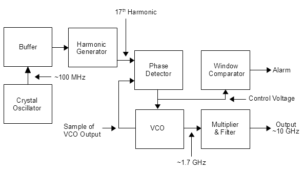
Figure 1. Block Diagram of the White Box Local Oscillator
For local oscillators set up like mine, the voltage-controlled oscillator (VCO) locks to the 17th harmonic of the crystal oscillator, and the output of the VCO is multiplied 6 times to create the injection signal. This is true for low or high-side injection. Figure 2 shows two possible frequency relationships for low and high-side injection.
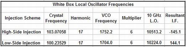
Figure 2. Frequency Relationships for Low and High-Side Injection.
The limits on the window comparator are set at approximately 4 and 16 volts. If the control voltage goes outside those limits, the comparator turns on the alarm output.
There are two circuit boards in the local oscillator. The board containing the crystal oscillator and phase detector is in the upper compartment of the enclosure and the VCO and multiplier/filter are in the lower compartment. There are photographs of the upper compartment in WA6CGR's document and in VE3SMA and VE3NPB's document on my downloads page. Figure 3, below, shows the lower compartment.
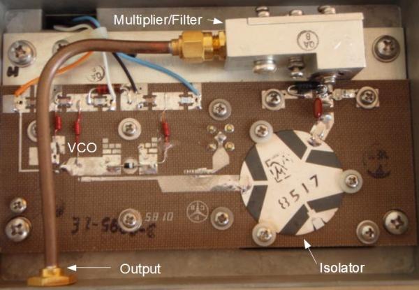
Figure 3. Lower Compartment of the White Box Local Oscillator.
Three things must work for the L.O. to provide a strong signal at the correct injection frequency:
- the VCO must oscillate at the desired 1.7 Ghz frequency when the control voltage is in the correct range
- the crystal oscillator must oscillate at the correct frequency strongly enough to drive the harmonic generator
- the output filter must be tuned to the injection frequency (six times the VCO frequency)
Tuning the VCO
I was unable to get a lock indication after changing to the low-side crystal, so I decided to start the troubleshooting process with the VCO. The base frequency of this oscillator (the frequency when the control voltage is zero) is determined by the pattern of traces on the pc board. The control voltage from the phase detector tunes the oscillator upwards from this base frequency. If the desired harmonic of the crystal oscillator is not within the tuning range of the VCO, the loop will not lock.
Figure 4 shows the VCO tank circuit as I received it, tuned to approximately 1.752 GHz. The base frequency is set by connecting the small pads to the main traces. You can see that two are soldered with a strap to the pad for the cathode of the tuning diode. When the loop was locked, the control voltage was approximately 11 volts as measured at test point E1 on the upper board or at the blue wire on the lower board.
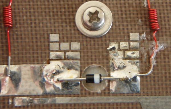
Figure 4. VCO Tank Circuit.
The signal from the VCO is strong enough that a frequency counter can measure it without connecting to the circuit. A short piece of wire held near the oscillator should couple enough signal to the counter.
I temporarily removed the blue wire connecting the control voltage to the VCO and measured the base frequency to be 1.711 GHz. Since this was above the desired frequency for low-side injection and the control voltage can only pull the frequency up, I had to add capacitance to the circuit to lower the base frequency and therefore the tuning range.
Since the range of tuning voltages centres on 10 volts, I temporarily replaced the blue wire with a 9 volt battery. This would put the VCO near the centre of its frequency range and allow me to tune it to the frequency for low-side injection, approximately 1.704 GHz.
To add capacitance to the circuit I added some copper tape beside the existing tuning strap and measured the resultant frequency.
When the frequency counter showed that I had the correct amount of copper tape, I soldered it in place. From the "I should have thought of that" file: the copper tape clearly had non-conductive adhesive because the output frequency plummeted. Soldering the copper tape meant that it now had a good electrical connection to the traces instead of a capacitive connection across the adhesive. Soldering increased the capacitive effect of the tape, lowering the frequency of oscillation. However, to get the correct frequency, all I had to do was trim the tape a bit at a time until the oscillator rose to the desired frequency. Of course I trimmed a little bit too much, but the tuning voltage range is wide enough that the VCO can still hit the desired frequency. Figure 5 shows the VCO tank circuit after tuning.
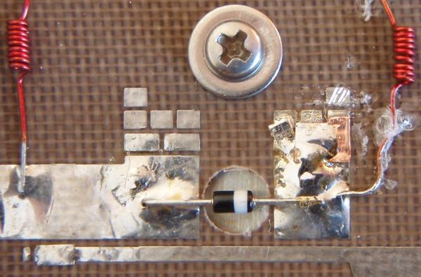
Figure 5. VCO Tank Circuit After Tuning.
Tuning the Crystal Oscillator
The output from the crystal oscillator with the high-side injection crystal was approximately -10.5 dBm as measured at the SMB connector test point with my HP 432A power meter. After I installed the low-side injection crystal, the output dropped by at least 2 dB. With the re-tuned VCO I was able to achieve lock at a control voltage of 8 volts, which proved that I had correctly tuned the VCO. However, the phase detector would not re-lock after power was cycled.
I did not complete tuning the crystal oscillator. I suspect that the problem with locking is the low output level. The crystal oscillator works well with the high-side injection crystal and, since the low-side injection crystal appears to come from the same manufacturer, I expect that it should work well in the circuit. The low power output could either be caused by the crystal oscillator circuit being unable to tune down to 100 MHz without modification or by a low-activity crystal. A second crystal did not fix the problem, so it seems likely the oscillator tuning range was the problem.
Tuning the Output Filter
The local oscillator output for high-side injection was approximately 18 dBm. Note that this level exceeds the rating of many power meters and an attenuator may be needed. After I tuned the VCO to approximately 1.711 GHz by removing the blue wire, the local oscillator output dropped to approximately 8 dBm. Clearly, the filter would need to be re-tuned once the VCO and crystal oscillator were working properly.
Copyright Keith Thomson, 2018.