
Language
English
Español
Related:
Introduction
Images
Version 2
Photos
Calculator
Bending the copper tubing isn't that easy, particularly if one doesn't own the right tools (like me). I invented an improvised bending tool. It's quite important to avoid deformations in the tube - it's necessary to pass the feedline through it later!

|
Raw materials: 5 meters of copper 8 mm tubing (5/16").
|

|
||
|
The two parts cut to the lengths indicated by the calculator. |
||||
|
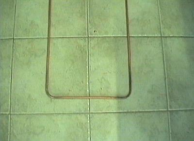
Example of the bending of the inner loop (the smaller one). Start
practicing with this loop, it doesn't have to pass the feedline, so
a little deformation is permitted.
|
|
||
|
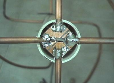
View from above. In the center, a small PC board can be seen, used to make the connections between the four tubes. Use fiberglass here! The pertinax boards don't stand the heat (literally). |
||||
|
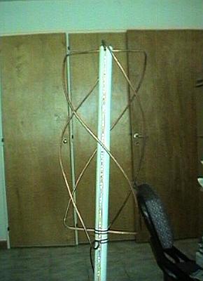
Side view of the almost terminated antenna - it's only missing the
top cover.
|
|
||
|
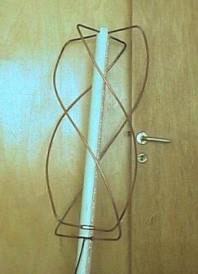
Another side view of the completed antenna. |
||||

|
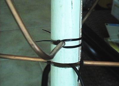
A view of the method used to fix the lower part of the loops.
Using a handsaw, I made a cut, just wide enough to receive the
tubing. I then fixed the tubes using cableties. It's not possible
to pass the tubes after bending, and bending the afterwards seemed
too risky...
|
|
||
|
Similar to the previous image - with a better view of the ties. |
||||
|
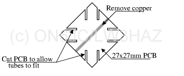
PC Board (fibreglass) prepared to receive the tube connections (top of
the antenna. Note the cuts to improve strength and ease soldering
|
|
||
|
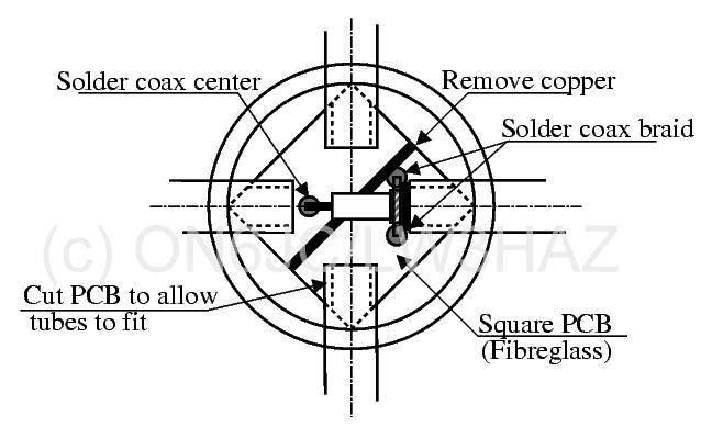
Connections made to the PC board, and the tubes mounted. Of course the copper tubes should be soldered to the board! |
||||
| (c) John Coppens ON6JC/LW3HAZ |