

Language
English
Español
Related:
Introduction
Images
Version 2
Photos
Calculator
|
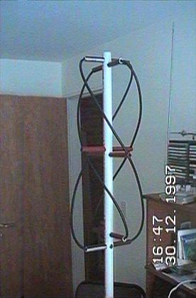
This will be the final result...
|

|
||
|
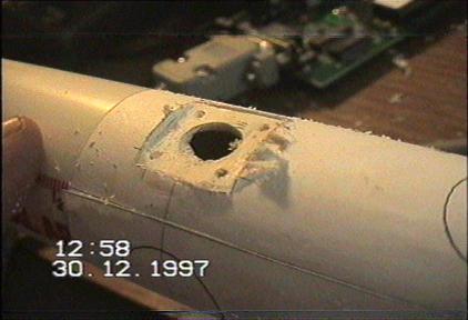
An example of how the element is mounted: Fix (glue) the template to the vertical support, at the correct separation. |
||||

|
Drill with a small (2.5 to 3mm) drill, just inside the circle, from each side of the support (don't try to drill through.
|
|
||
|
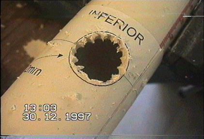
Remove the inner part. |
||||

|
File (with a round file), and adjust the diameter to the horizontal supports.
|
|
||
|
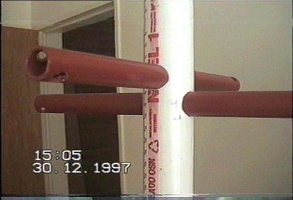
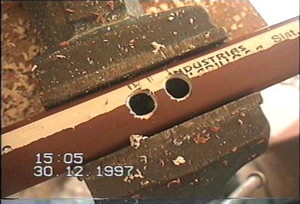
Another example, here are the middle supports. Take note of the orientation of the holes drilled for the coax support. |
||||
|
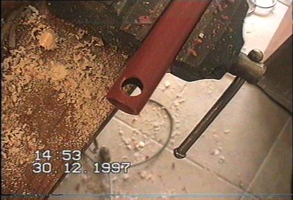
Drill the horizontal support at each end (90 degrees difference), to
pass the coax cable in the right direction.
|

|
||
|
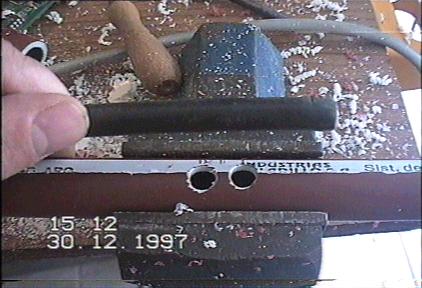
Similarly, prepare the holes for the BNC connector. Drill the mounting holes with the right diameter for selftapping screws. |
||||

|
The drill the center hole for the connector.
|
|
||
|
File, to obtain a flat surface for the connector. |
||||
|
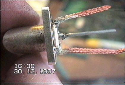
Here the BNC connector, being prepared before mounting.
|

|
||
|
Idem. |
||||
|
This is the second support being prepared for connection to the outer loop. These holes should be on one side only!
|
|
||
|
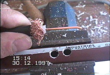
The cable being prepared for connection to the outer loop. |
||||

|
Remove the outer sleeve for about 4 cm.
|
|
||
|
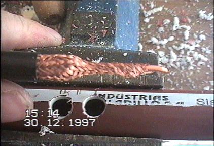
Without cutting the braid, remove inner polyethylene isolation. |
||||
|
Twist the braid, joining it with the inner conductor. Then bend them, near the end of the sleeve, at 90 degrees, to help passing them through the holes.
|

|
||
|
This is the correct way to connect them with the outer loop. |
||||
| (c) John Coppens ON6JC/LW3HAZ |